

Salam Everyone!
- I've seen many students, troubling in the concepts of Class Designing and Diagrams. So, I've decided to make a much simplified Tutorial on Class Diagrams and Modelling using Unified Modelling Language (UML). It's mainly based on a Document, made by a Student of our University, and other guides (details are in the Credits below). I've just combined everything in one place. I hope U will find it useful!
- I've summarized all the Concepts in three Sections. These Sections are represented by Steps here.
Requirements
- Software for making Diagrams (MS Visio etc.) OR Online Framework (like LucidChart)
- Basics of Programming in any Language supporting Object Oriented Language (OOP)
- Motivation, Passion n Patience
Index
- Section A - Basics
1) - Modelling language (UML)
2) - Modelling techniques
3) - Data modelling techniques
4) - Domain modelling
5) - Levels of modelling
6) - UML class diagram
- Section B - Associations
1) - Association basics
2) - Unary association
3) - Ternary association
4) - Multiplicity of ternary association
5) - Aggregation
6) - Shared aggregation
7) - Composite aggregation
8) - Implicit association
9) - Parallel paths
- Section C - Inheritance
1) - Inheritance
2) - Generalization and specialization
3) - UML Notations
4) - Generalization sets
5) - Reading Model with generalization/specialization
- So Lets Begin ...
Step 1: The Basics
We'll start from some definitions
Unified Modelling Language
- Modelling Language
Modeling language is any Graphical or Textual computer language that provisions the design and construction of structures and models following a systematic set of rules and frameworks
- Unified Modelling Language
Unified Modeling language (UML) is a standardized modeling language enabling developers to specify, visualize, construct the Document artifacts of a software system. Thus, UML makes these artifacts scalable, secure and robust in execution. UML is an important aspect involved in Object-Oriented software development.
- What should you know about Modelling techniques?
The techniques using which you draw the models are known as Modelling techniques. Modelling techniques range vary from Textual to Formal.
Textual means completely descriptive (written like English sentences)
Formal means completely symbolic (written like Program statements)UML is a special language which is neither too descriptive (textual) nor too symbolic (formal) but lays somewhere between the two.
- Modelling techniques for Information System (IS)
There are many modelling techniques for IS some of them are there.
• Entity Relationship Modelling
• UML Class diagram
• UML Statechart
• Flow Charts
• Process Flow Diagrams
• Petri Nets
• Event-driven Process Chains (EPC)
Domain Modelling
- Definition
The Domain Model is your organized and structured knowledge of the problem. The Domain Model should represent the vocabulary and key concepts of the problem domain, and it should identify the relationships among all of the entities within the scope of the domain.
A Domain Model is a visual representation of conceptual classes or real-world objects in a domain of interest.
- Code-Management
It is important for a programmer to understand the core concepts of the project so that he/she may develop a software with proper Code Management.
Where code management means that the code is so flexible that later on we can make changes according to the requirements and situations. It plays an important role in designing and coding complex Applications, which require lot of Mathematical and Logical programming. Modelling Languages help us to design our Programs with Proper Code Management, and best Optimization possible.
- Levels of Domain Modelling
There are 2 levels of modelling, Level 0 and Level 1.
Level 0
In level 0 we usually make the instances or objects. For example, Ali, Zara and Shahid are the instances.Level 1
In level one we combine all the instances from level 0 and make a class. For example, STUDENT Class contains Ali, Zara and Shahid.
MODEL and MODEL Validation
When we have to make models, we move from level 0 to level 1.
When we have to verify the model to check that if its correct or not, we move from level 1 to level 0.
Classes in UML
- Class Diagram in-terms of UML
In Software Engineering, a class diagram (in the Unified Modeling Language) is a type of Static structure diagram that describes the structure of a system by showing the system's classes, their attributes, operations (or methods), and the relationships among objects.
A class is a collection of many instances or you may say that it's a Blueprint of the object.
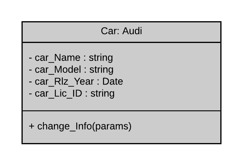
- Representation of a Class and it's Diagram
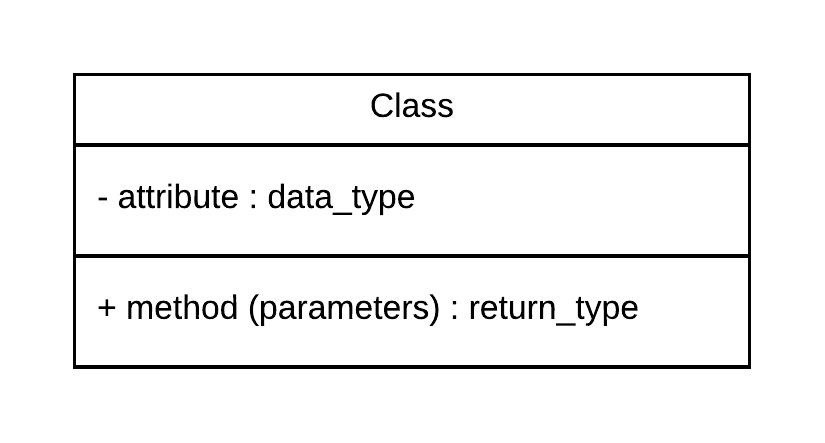
In UML, a class represents an object or a set of objects which share a common structure and behavior. They're represented by a rectangle that includes rows of the class name, its attributes, and its operations as shown in figure below.
A UML Class Diagram is made up of:
- A set of classes
- A set of relationships between classes
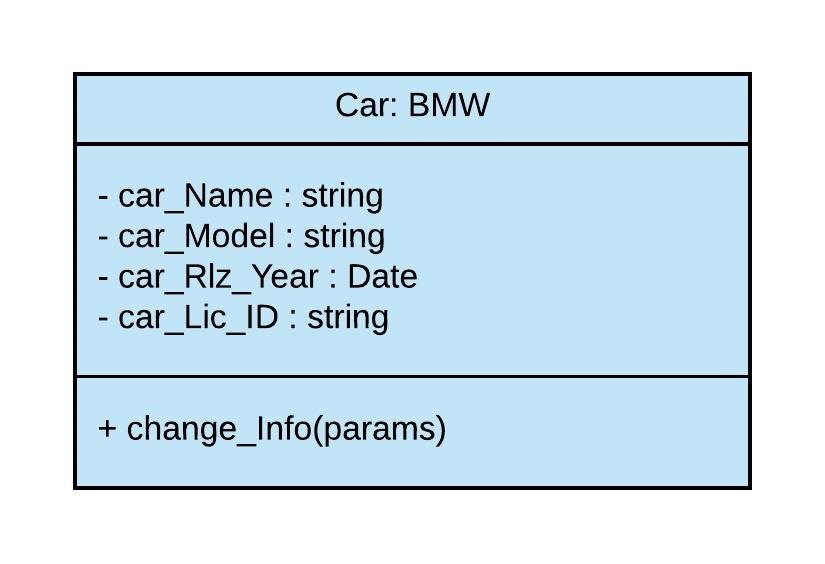
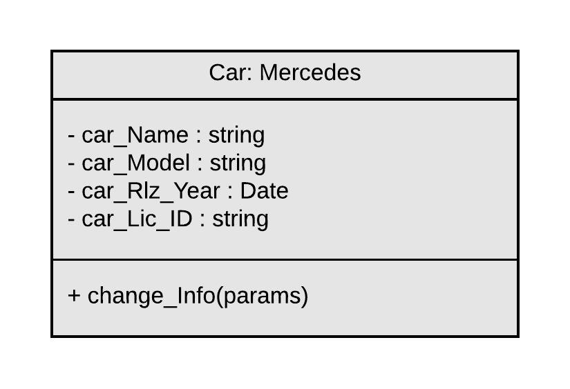
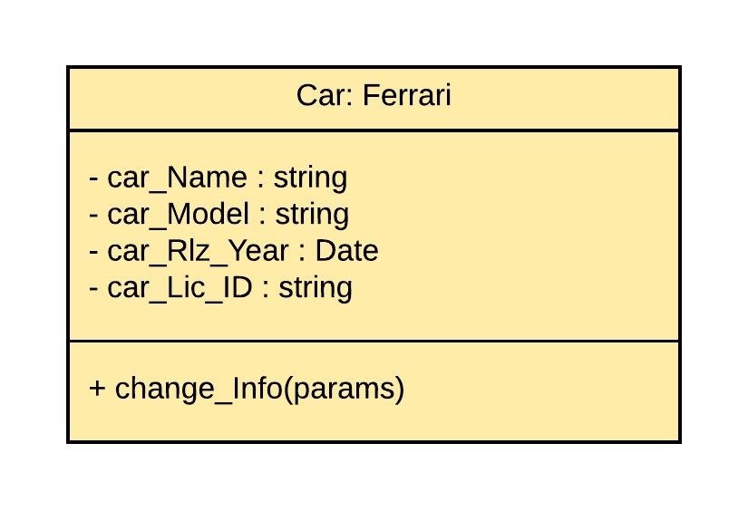
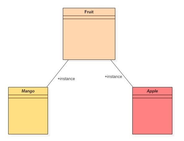
- Representation of Instances of the Class
As we know that the class instances are actually the objects of class so we may say this the representation of objects. An object diagram in the Unified Modeling Language, is a diagram that shows a complete or partial view of the structure of a modeled system at a specific time. Examples will make it clear.
Instances of a specific class can also be represented as :
- Types of Classes
There exist two types of classes in UML.
Abstract / Parent Class
Declaring a class as Abstract means that it cannot be directly instantiated, which means that an object cannot be created from it. ... Abstract classes require subclasses to further define attributes necessary for individual instantiation. Abstract classes contrast with concrete classes, which are the default type. Generally, their Names are written between : "<<" and ">>" or in Italic.
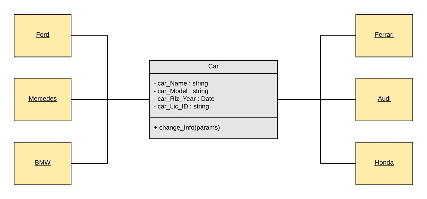
Child Class / Sub-Class
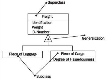
Child Classes or Sub-Classes are the classes, which are directly Inherited from the Abstract Class or Parent Class. All the Instances are created via the Sub-Classes, if there exist Abstract Class. The concept of Inheritance will be discussed in Section - C, but here is a brief view. Following is an example
of workers in a corporation. This will give you a view :

- Sections of Class
There exist three sections (or portions) in the Class, in UML
Section A - Name
At the upper-most section of the class, the Name of the class is listed. The name of the class is written in Italic, if it's an Abstract class
Section B - Attributes and Data_Type
A significant piece of data containing values that describe each instance of that class is known as Attribute. An Attribute is actually a name which describes the property of object being modeled. Attributes are also known as fields, properties and variables. Attributes are written just below class name. Attributes begin with their access specifiers (these will be discussed next).
In UML diagrams, Data Types are model elements that define data values. You typically use data types to represent primitive types, such as integer or string types, and enumerations, such as user-defined data types. A data type is similar to a class; however, instances of data type are identified only by their value. Data types are written just after the attribute, following with ":" sign. Look at the example below.
Section C - Methods / Functions
Methods, also called functions or operations, are listed in the lower-most section of the class in UML. Methods are the specific functions, which are made inside of the class, to modify attributes or to perform a specific task. Methods are accessed by the objects initialized by that class. Methods allow you to specify any behavioral feature of a class.
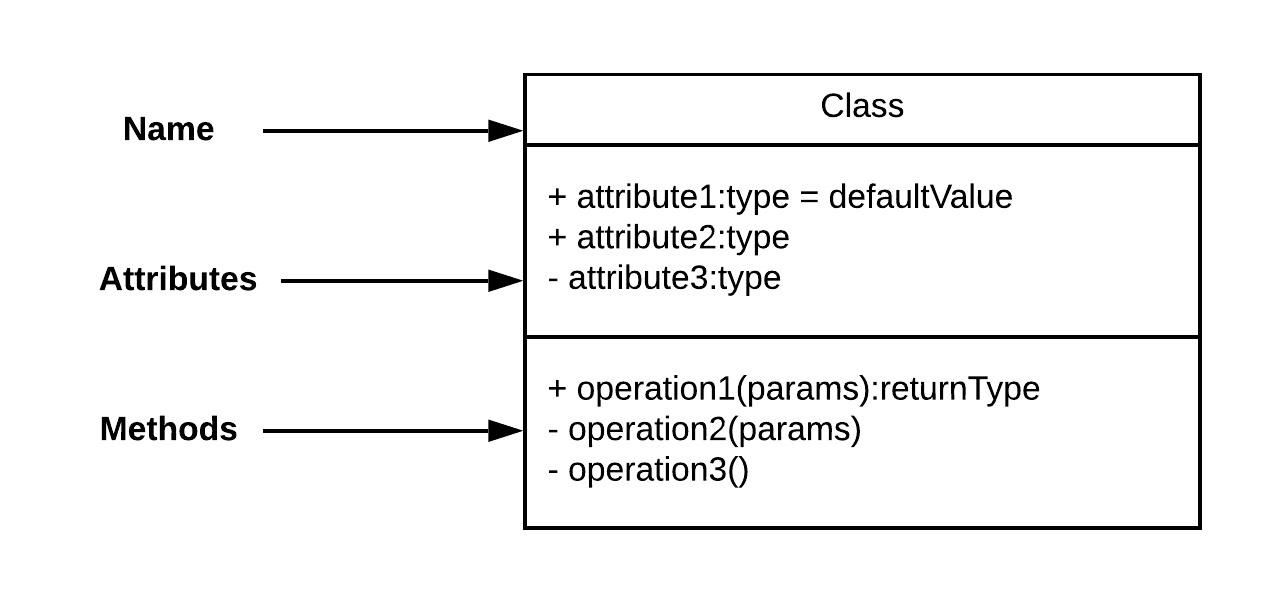
- Access Specifiers
Access Specifiers show the Visibility of the contents of the class to the outer System. In UML, they are represented by symbols. There exist 4-types of Access Specifiers.
" - " for : private
" + " for : public
" # " for : protected
" ~ " for : package
- Private means the attribute or method, which is set to be private can only be accessed within that class only.
- Public means the attributes or methods, which are set to be public can be accessed from anywhere in the system. It's completely opposite of private.
- Protected means the attributes or methods, which are set to be protected can be accessed only by that class, and it's sub-classes.
- Package means the attribute or method, which is set to packaged can be used by any other class, as long as it's located in the same package.
So, that was the brief intro of everything you needed to know about the classes, and their instances. Now, we'll move towards the relationships of multiple classes.
Step 2: Relationships of Classes
- Relationships between the Classes
Classes are interrelated to each other in specific ways. In particular, relationships in class diagrams include different types of logical connections. The following are such types of logical connections that are possible in UML:
- Association
- Directed Association
- Reflexive Association
- Multiplicity
- Shared Aggregation
- Composite Aggregation
- Inheritance/Generalization
- Realization
We are going to study few of them in this section with complete detail. Others will be discussed in next Section.
Association
We'll discuss association in more detail because it causes complications in the students, while learning UML. They often confuse it with other types of relationships in the classes. We will also discuss it's types here.
Association states that there is some kind of a link between multiple classes. It is a structural relationship that represents that, specific objects can be connected or associated with another object inside the system. Following constraints can be applied to the association relationship.
Implicit – As the name suggests, the Implicit constraints define that the relationship is not visible, but it is based on a concept. This concept will be used further in this Guide.
For example: There are two Companies A and B. Managers of both companies sign a project. All this scenario shows some kind of relationship between the two managers and the company's project, but there is an indirect relation between the staff working on this project. Hence there is an Implicit Association between the staff of company A and company B.
Below are some other constraints of association, which are not mainly used in basic UML. We'll not discuss them further in our guide.
Ordered – Ordered constraints specify that the set of objects at one end of an association are in a specific way.
Changeable – Changeable constraint specifies that the connection between various objects in the system can be added, removed, and modified as per the requirement.
addOnly – It specifies that the new connections can be added from an object which is situated at the other end an association.
Frozen – It specifies that when a link is inserted between two objects, then it cannot be modified while the frozen constraint is active on the given link or a connection.
A class with assigned Association, is called an Association Class
Types of Association are below
- Reflexive (Unary) Association
The reflexive (a.k.a. Unary) association is a subtype of association relationship in UML. In a reflexive association, the instances of the same class can be related to each other. An instance of a class is also said to be an object.
Reflexive association states that a link or a connection can be present within the objects of the same class.
When the association is between multiple instances of the same class, then it's called reflexive or unary association
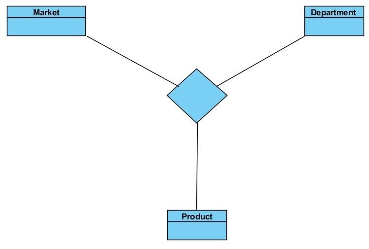
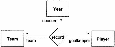
- Ternary Association
As the term "Ternary" (means 3) explains the type of association, in Ternary Association there is a link between three classes or instances of three different classes. Watch an example below :
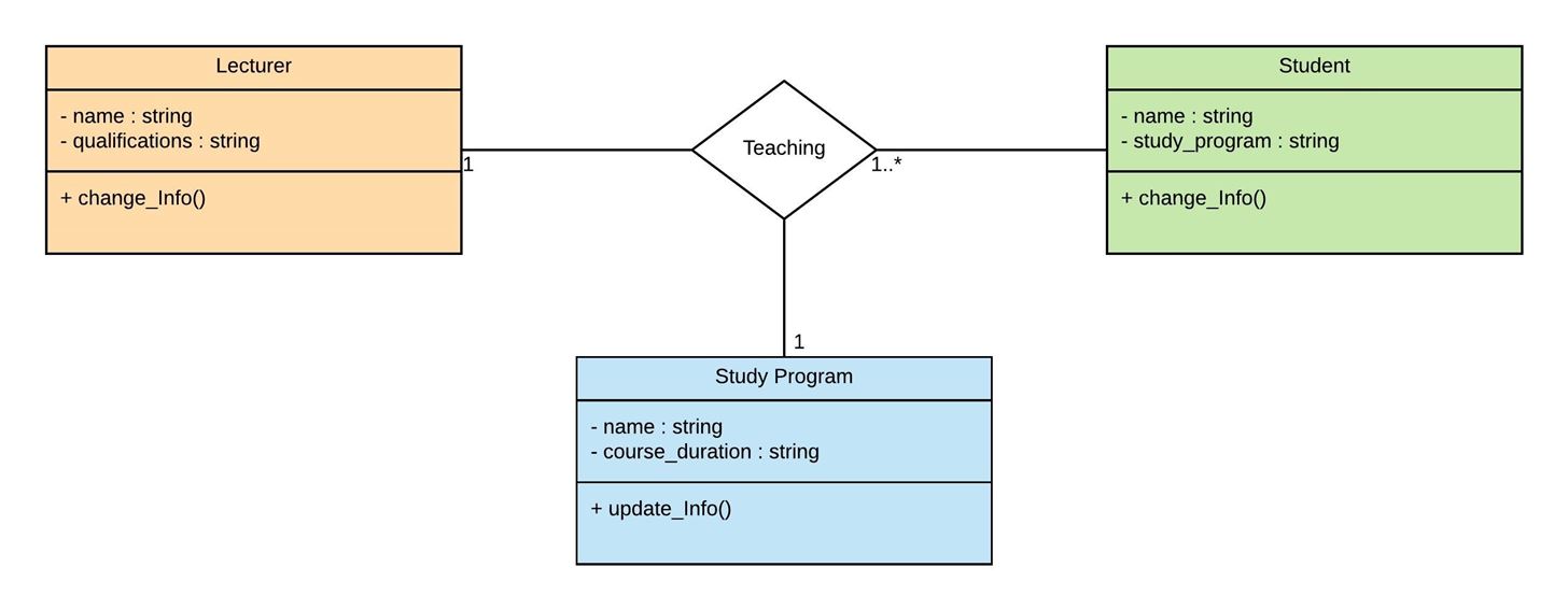
- Learn via an Example
It's not very tough to conceptualize the relationship between classes : Lecturer, Student and Subject.
Just take a Real-Life example : This diagram can clearly explain that, let's say Sir : Saqib Rasool (who is an instance of Lecturer class) teaches the Students of CS, (which are the instances of Student class) and he teaches Object Oriented Programming to his Students. (which is the instance of Subject class). All the instances of 3 different classes have relationship, such relation is called Ternary relationship.
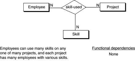
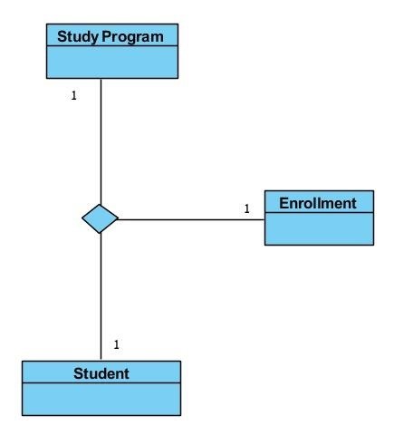
Multiplicity of Ternary association
Multiplicity means that one or more instances of a class may be related to one or more instances of the other class or classes at the same time. This can also be understood by same example as given above.
Sir : Saqib is one instance of class : "Lecturer", he teaches many students let say 53. All 53 students are actually instance of class : "Student". So, we can say that one instance of class Lecturer has relation with many instances of class Student. And, all are also associated with the same Subject Program, which is obviously Object Oriented Programming.
Watch more example images below, for much better understanding :
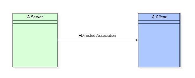
- Directed Association
As the name suggests, the directed association is related to the direction of flow within association classes.
In a directed association, the flow is directed. The association from one class to another class flows in a single direction only.
It is denoted using a solid line with an arrowhead.
Example:
You can say that there is a directed association relationship between a server and a client.
A server can process the requests of a client. This flow is unidirectional, that flows from server to client only. Hence a directed association relationship can be present within servers and clients of a system.
Dependency Relationship
A dependency means the relation between two or more classes in which a change in one may force changes in the other. However, it will always create a weaker relationship. Dependency indicates that one class depends on another.
- Aggregation
Aggregation is a way of composing different abstractions together in defining a class. In Aggregation, we represent a dependency relationship between multiple classes. Like, one or more classes depend on a single class. There are two types of Aggregation, Shared Aggregation and Composite Aggregation.
We will take some real world examples for Aggregation ...
Examples of Aggregation Relationship include the relationship between : Class-Room and the Educational Institute, Tables and Chairs in Hall, CPU-Components in a Computer, wheels in vehicles etc.
- Shared Aggregation
A Shared aggregation relationship can be described in simple words as, "an object of one class can own or access the objects of another class."
In a Shared aggregation relationship, the Dependent object remains in the scope of a relationship even when the Source object is destroyed. Take a look at an Example below:
Example
Consider a Car class, which can be defined to contain other classes such as engine class, seat class, wheels class etc.
In these examples, the Dependent Classes can exist on their own, like, the wheels, seats, and engine can exist without the Car, and so their classes. It's an Example of Shared Aggregation. Take a look at another simpler example below,
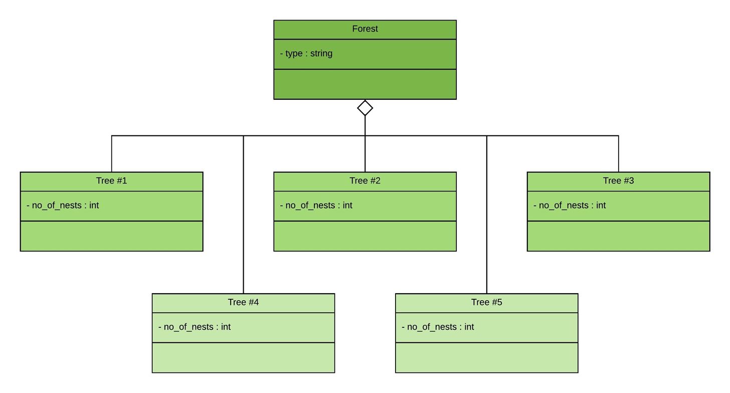
Consider a Class for Forest, which is a class made by the aggregating (combining) many classes of Trees. But when we separate the trees from the forest, the trees, will not cease to exist. But they will survive without a forest for sure. This is what, happens in Shared Aggregation. Re-Read the Shared Aggregation topic for better understanding.
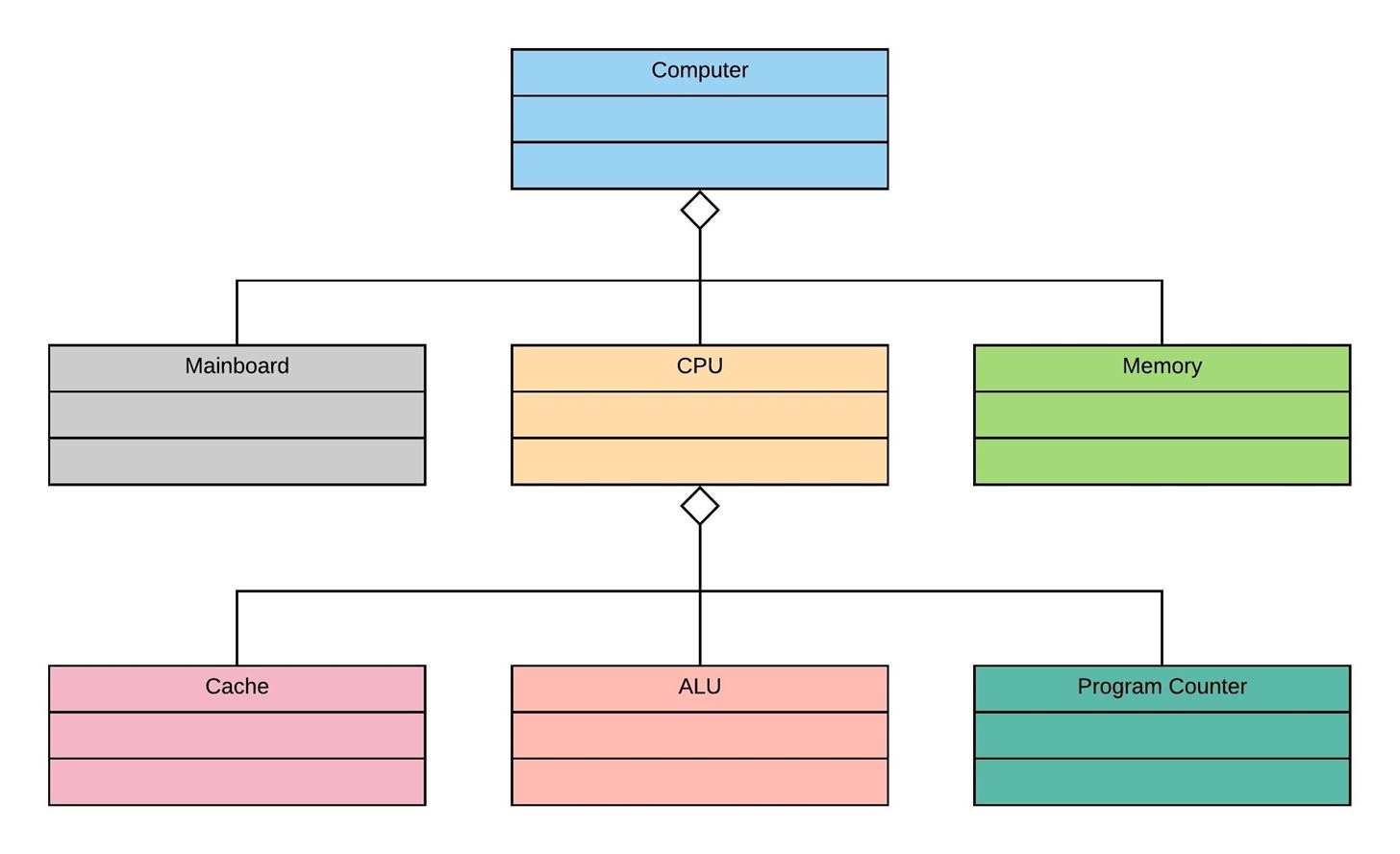
Representation:
Aggregation is represented as Hollow tilted box / Diamond towards the Source-Class. Take a look at example below :
- Composite Aggregation
Composition or Composite Aggregation is the sub-type of aggregation, which is the relationship between two or more classes or objects, when both are completely dependent on each other. Means, one can't exist without the other. It's opposite to simple aggregation, where the Dependent asset could live without the Source asset.
Composite aggregation is a subtype of aggregation relation with characteristics as:
- It is a two-way association between the objects.
- It is a whole/part relationship.
- If a composite is deleted, all other parts associated with it are also deleted.
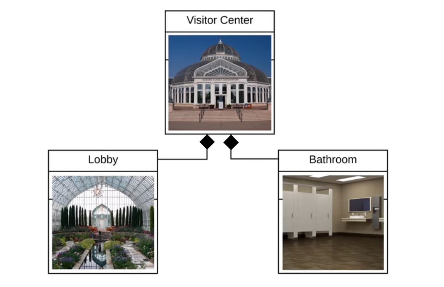
- Representation
Composition is represented as Filled Diamond positioning towards the Composite Class.
Consider the following example :
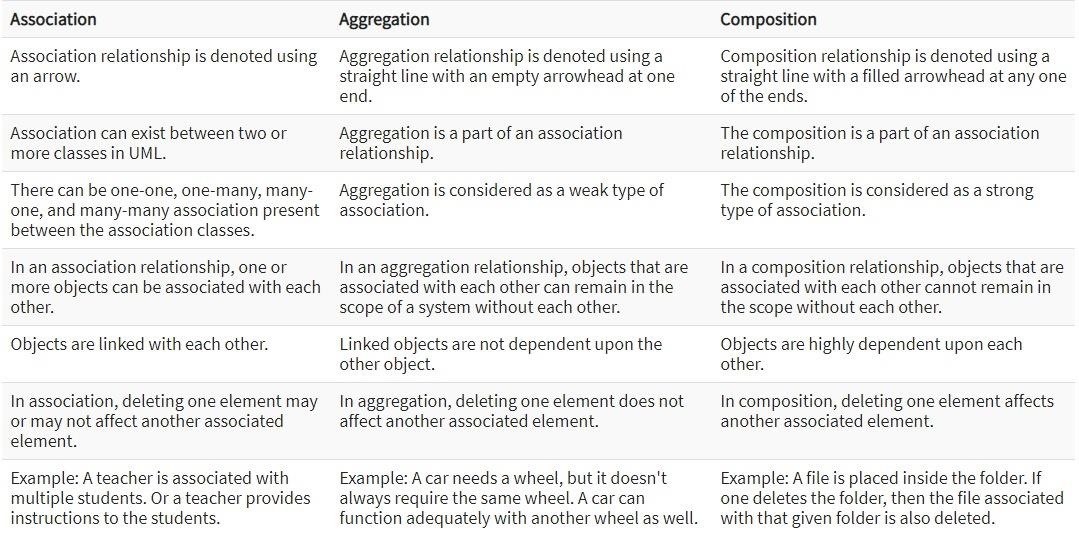
Take a brief look at their comparison, if there's any confusion
We've discussed the relationships between the Classes and and the Objects at above article. Sometimes, a single class is being shared by many other classes at the same time. It may be Association relationship or Aggregation Dependency. Those multiple PATHS, which connect that class with other different classes (to which its connected with) are called Parallel Path ways.
Now, one last thing, sometimes, we want to specify multiple relationships of the single class with other class or classes. For Example :
For this purpose, we use the concept of Multiplicity!
Multiplicity
First, understand the concept of Cardinality, if you haven't,
Cardinality
The number of elements in a set or other grouping, as a property of that grouping. This Phenomenon is called Cardinality.
Example #1
Consider the following sets :
N = {1, 2, 3, 4, 5, ...}
W = {0, 1, 2, 3, 4, 5, ...}These are the sets of Natural and Whole Numbers. We can say, that the Cardinality exist in "N" and "W". Because both N and W have multiple values in them. Let's take another example related to Computer Science.
Example #2
Consider following two vectors :
Students = {Shaban, Ali, Usama, Sami, Habib}
Administrators = {The_Legend, Dr. Hanz, Phillip, Jesse, JayZee, R37r0, V}Here, in these two vectors, there exist a cardinality in "Students" and "Administrators" vectors, because they have multiple members inside them. They are pointing towards multiple Objects.
Similarly, Cardinality also exist in the case of classes. If a class has multiple Objects assigned to it, we can say that cardinality exist in that class.
Now, let's move towards the concept of multiplicity ,
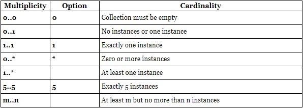
Multiplicity in UML allows to specify the Cardinality - i.e. number of elements - of some collection of elements.
Let's say, there are 100 Students in a Batch. All of them are assigned to a Specific subject. Look at the diagram below :

To show such relationship, we use some terms to represent that relationship of multiplicity. These terms are as follows :
Now, the question arises, how can we read and specify multiplicity? The answer is simple.
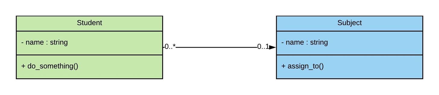
It depends on the reader or the observer, who's viewing the diagram, let's illustrate it via the following example :
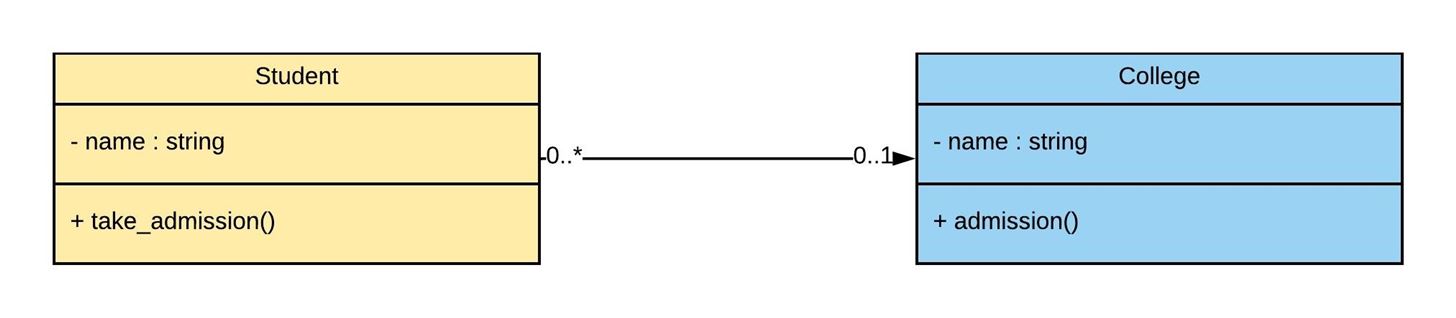
It's obvious that there's a cardinality exist in this relationship, so to represent that cardinality, we have to use the Multiplicity concept. You can see, we've used the terms of multiplicity in the diagram : 0..* and 0..1. Let's understand this concept. These terms are read from one class towards the other one. If we read from the college class :
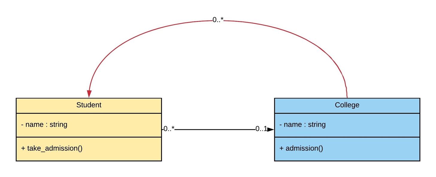
Now, let's take a look from the opposite side (Student to College) :
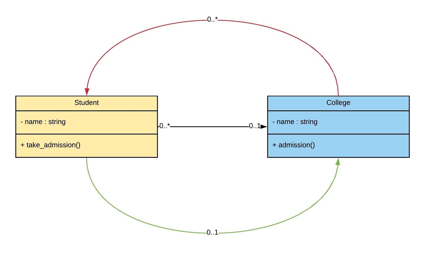
Hence, it's clear that the Assignment of Multiplicity depends on the viewer's perspective. And so, it's represented on the single line joining the Student and the College class as shown above. For more information, check the UML-Diagram Site.
Let's move on to Section C
Step 3: Inheritance
We have covered the basics of Association and Dependency Relationships, there is another concept which is a bit different of these relationships. And that's Inheritance. If you have the concept of Inheritance in OOP, then it's the same in UML. Inheritance is divided in two concepts at the bases of their use. These are Generalization and Specialization. The method behind these two concepts is completely Identical, just the names are given based on the use of Inheritance Concept.
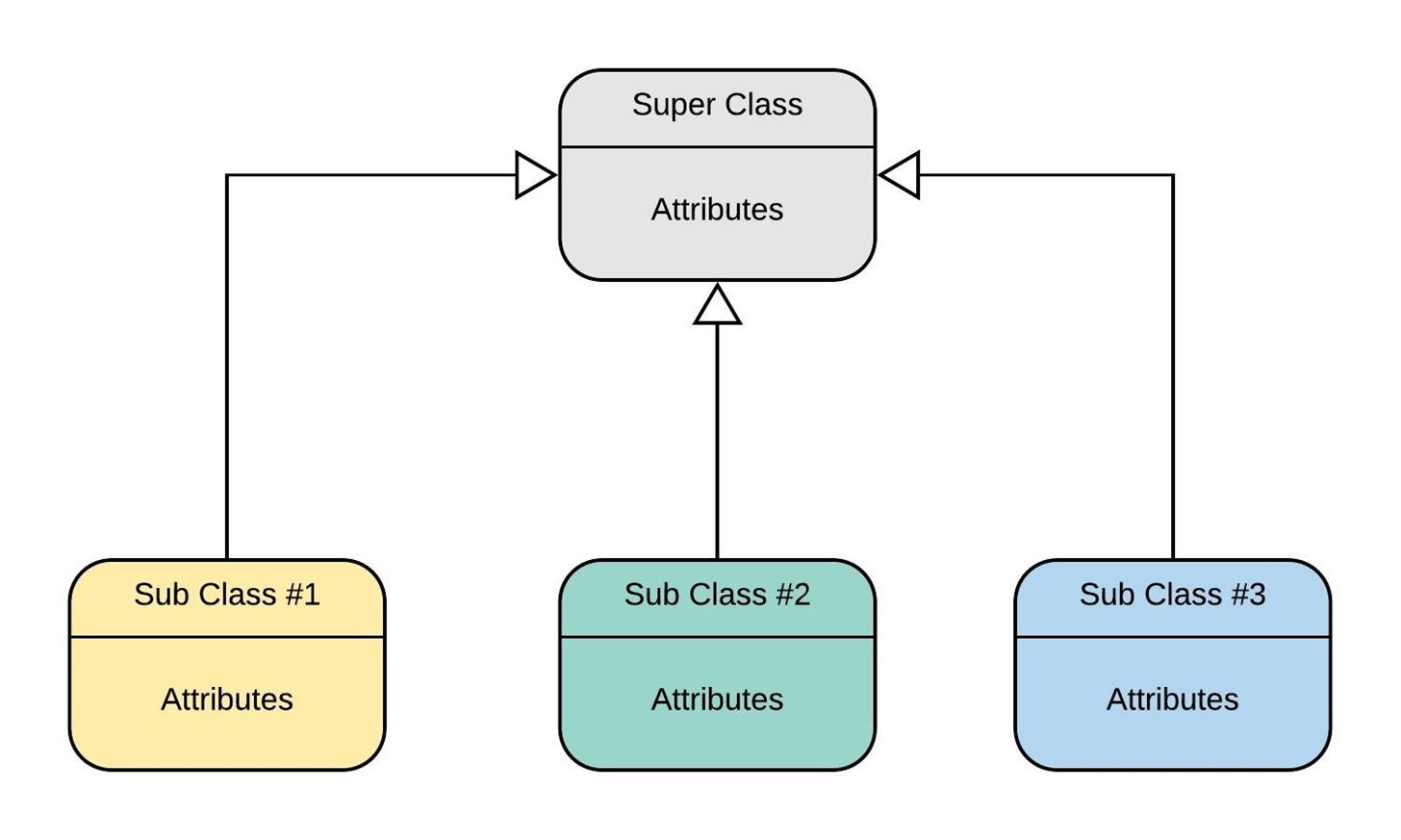
- Representation in UML
Generalization in UML Notations is represented as the Hollow Triangular shaped Arrow, pointing towards the SuperClass from the SubClass / Child-Class.
Generalization and Specialization
Generalization is the process of extracting shared characteristics from two or more classes, and combining them into a generalized Superclass. Shared characteristics can be attributes, associations, or methods.
Everything is clear in the example given below.
Specialization means creating new subclasses from an existing class. In the above given examples, the two subclasses are the specialized classes
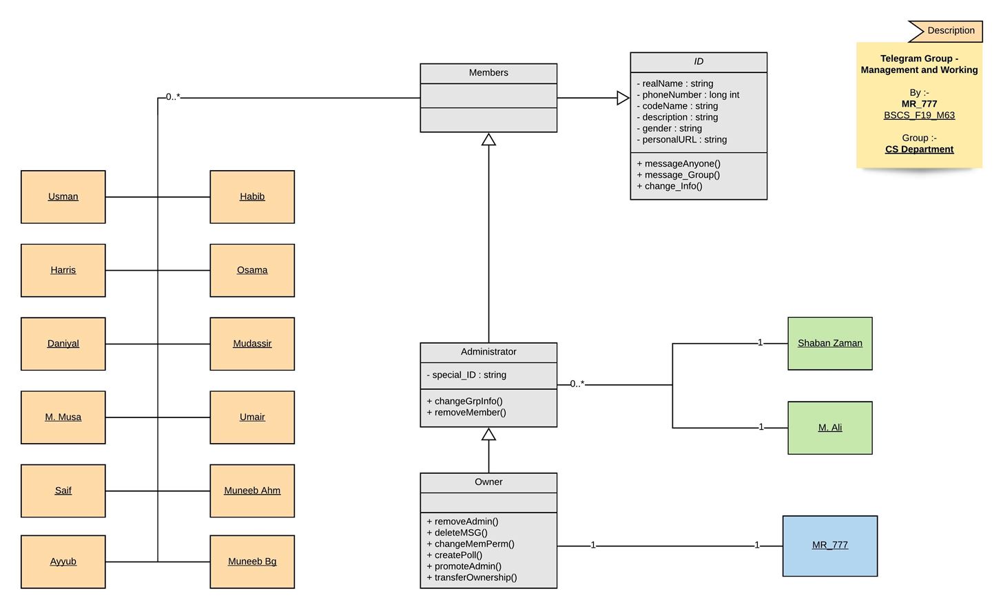
Below is the Management System of Telegram Group of 2nd Semester. Take a Look :
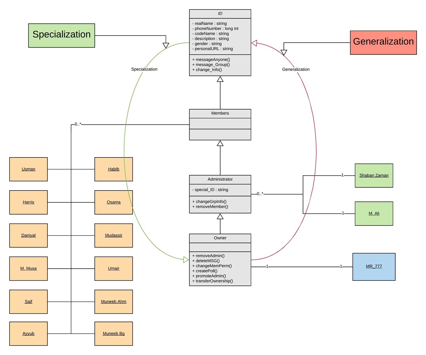
This diagram can be represented in-terms of Generalization and as well as in Specialization. Take a look below :
- Different ways of representing Inheritance
Finally, there are some different ways of representing the Inheritance Relationship, between the assets. Two of them are below :
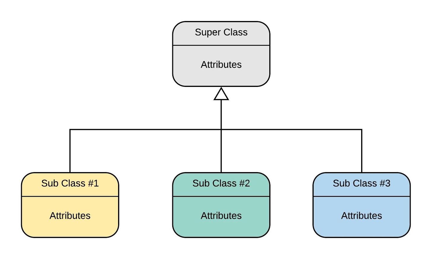
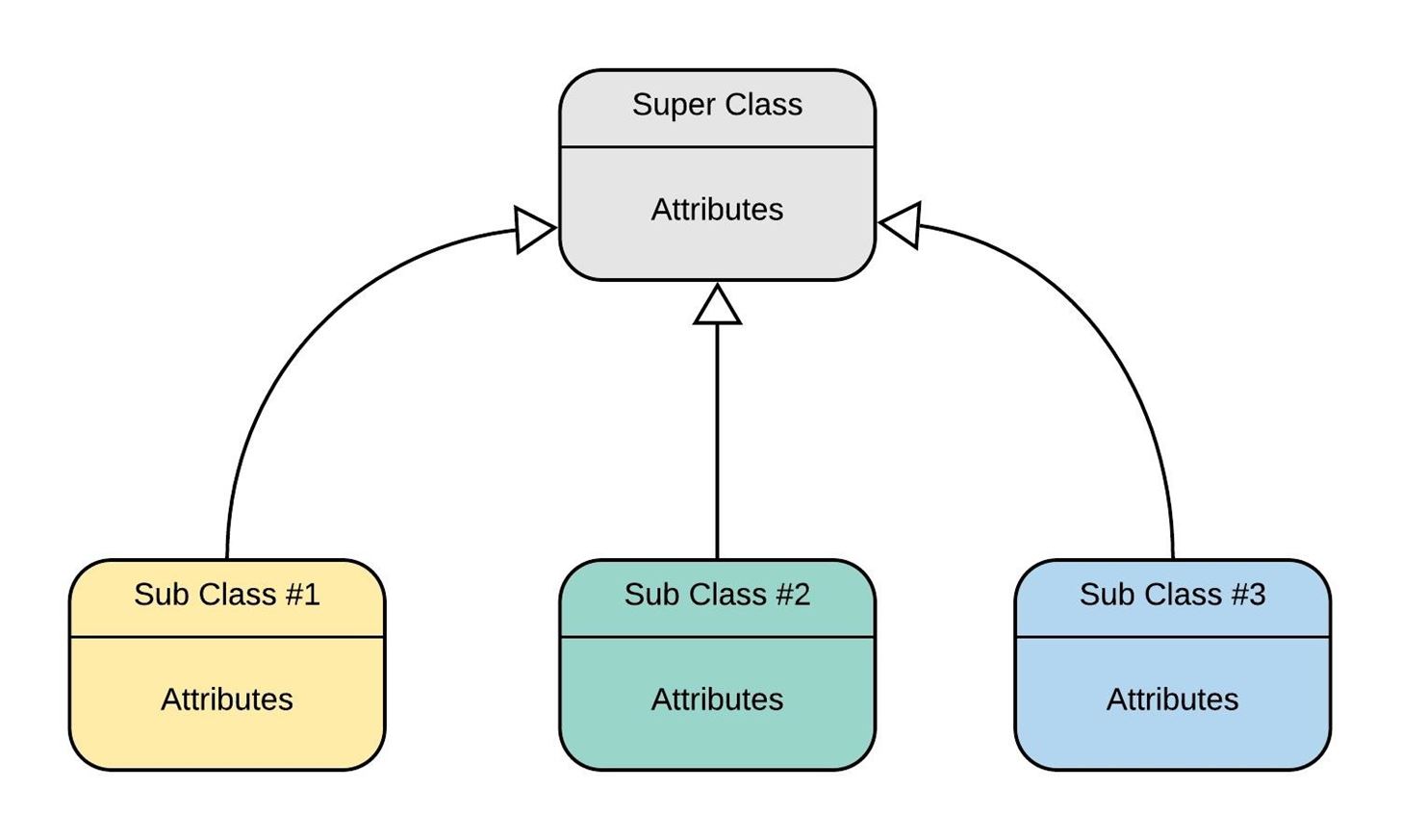
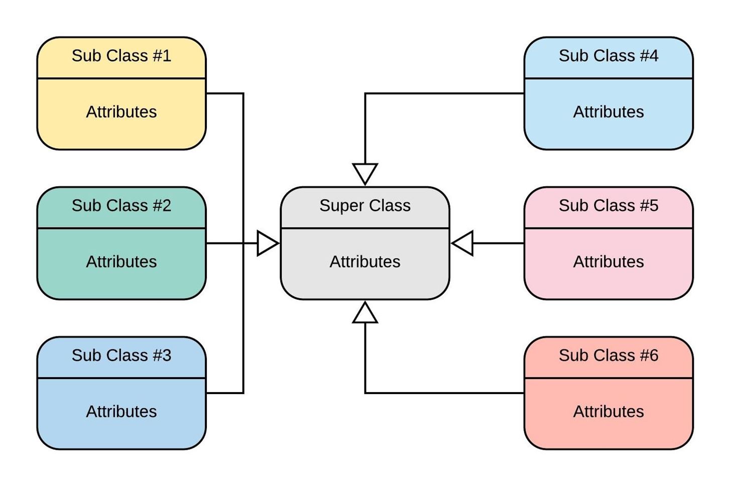
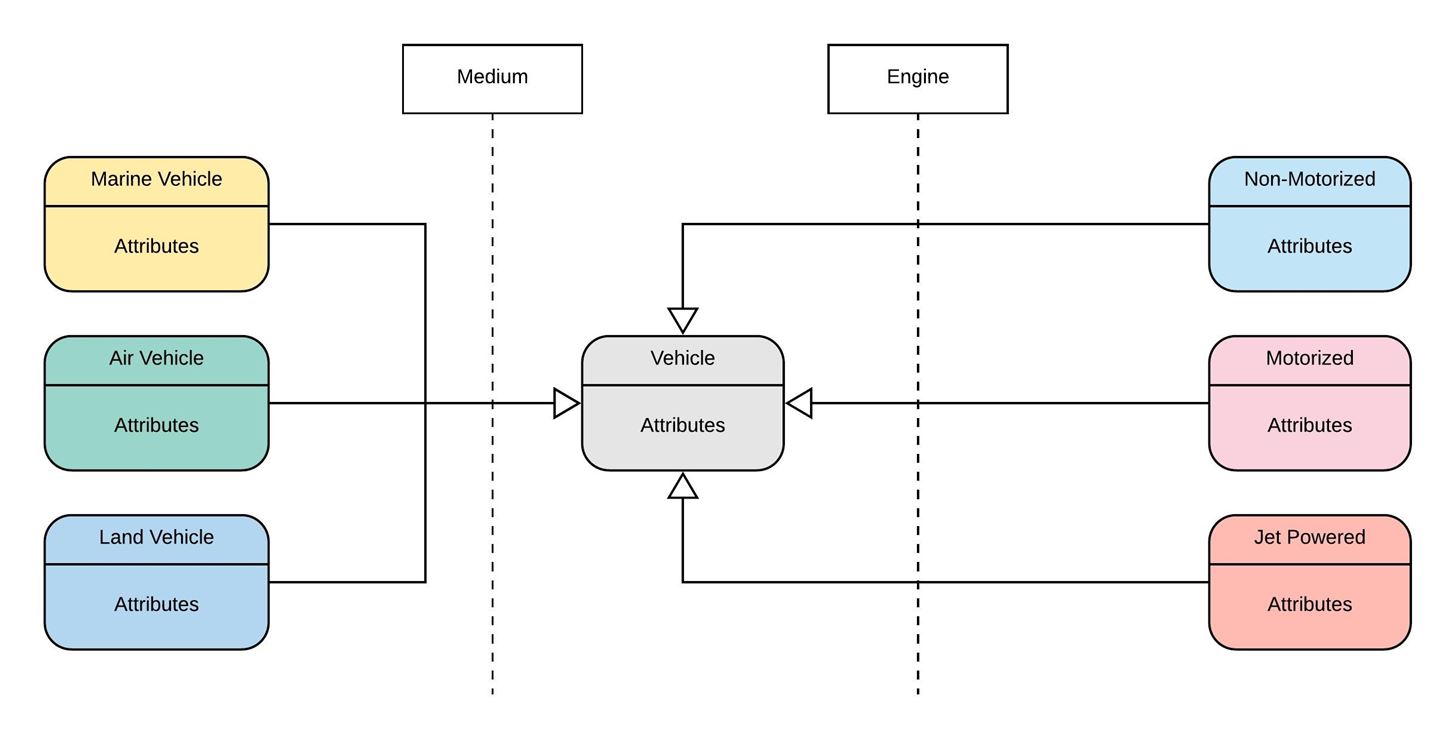
You can also create some Generalization Sets, according to the conditions like the following diagram :
So. Here ends the Section C!
Final Words
I hope The Class Designing is completely explained in this guide / article. If you have any questions or queries, you can comment in the comment box below. I've created a Telegram Community for the Students of our University, to answer their queries there. Members who are not the part of our University are also free to join us. We usually have Quizzes daily. You can join us for Syllabus Updates and Announcements related to our University (We have a separate community for that, click the link to join). I hope you had a Nice Experience with my Guide! If you wanna join us, Join via the Links below :
- CS Community on WhatsApp for CS Students (International)
- Telegram Discussion Community for answering your Queries
- Telegram Resources Zone for Syllabus Updates and other Announcements. It's my Channel. Complete Syllabus of every subject can be found here.
Credits
I would like to give thanks to the following, whose information I use to build this guide :
- The Student of our University, whose Document I used to build the main structure of this guide.
- UML Course at edX
- YouTube Tutorial by LucidChart
- UML-Diagram Site
- SourceMaking Site
- H4ck3R_777, everybody may know about him on Null-Byte. His tutorials are always on Active list on Null-Byte. I'm using his design to make my Guide. Thanks to him!
- Mr. Google, who helped me find meanings of many words, and to minimize my spell-mistakes :)
- And many Students, who motivated me to build this guide.
Thank You Everyone!
I will keep this page Updated for the new content.


1 Response
Salam Everyone
Share Your Thoughts