


A relay is an electrical component that works like a light switch, where it's turned on or off with an electrical signal. By connecting a relay to a Wi-Fi connected microcontroller like an ESP8266, you can build a connected switch that can be controlled from the web browser of any device connected to the same Wi-Fi network — all for just a couple of dollars.
How an Electrical Relay Works
When you want to turn a device on or off without being present, an electrical relay can take the work off your hands. Designed to switch on and off in response to an electrical signal, a relay can be used to control the power supply to nearly any device. This means that a relay can be combined with inputs like a motion sensor or microcontroller to make it react to the environment or to commands.
On the inside, a relay has three power inputs: a terminal that is normally connected to power, a terminal that is normally disconnected from power, and the "common" terminal where we plug in the power we want to switch. Another three inputs are used to connect the relay to a power source and signal used to switch on and off an electromagnet inside the relay.
Kody/Null Byte
When the signal input gets power, the electromagnet turns on and completes the circuit, causing the normally disconnected circuit to connect to power, as well as the normally connected terminal to disconnect from power. By choosing which terminal we plug into, we can decide if we want our switch to normally be connected or disconnected to power before we sent it a signal to switch.
Adding an ESP8266 Board
Once we have a relay able to respond to a sensor, we can control it even more precisely by communicating with it through a microcontroller. When the microcontroller we connect it to also has the ability to connect to Wi-Fi, it becomes possible to operate the relay remotely from any device connected to the same network. The ESP8266 is a popular chipset for prototyping IoT devices in Arduino and happens to be perfect for this application.
Because the ESP8266 chip is so easy to program, we can select a development board like the D1 Mini or the NodeMCU to combine with a power relay. These ESP8266-based boards are cheap and easy to work with, costing around $2.50 when purchased from Chinese suppliers online. If you're willing to wait for overseas delivery, entire home automation projects become relatively cheap to add Wi-Fi functionality to. When purchasing off Amazon or the like, it's still very affordable.
A hacker can get in on the fun by programming the relay to power on a hidden device like a Raspberry Pi when needed. They could also disconnect a critical device like a firewall in the future if the hacker gets physical access to the equipment. This functionality can even be extended to allow turning the relay on and off from over the internet, not just a shared Wi-Fi connection.
Using aRest for Remote Control
One of the best free platforms for controlling Arduino devices remotely is aRest. This project, written in Arduino for the ESP8266 Wi-Fi chip, hosts a REST API that allows easy communication with any pin of the microcontroller. This means you can add some code to your ESP8266 device, locate it on your Wi-Fi network, and then send commands to it from any browser connected to the same Wi-Fi network.
While the aRest project is intended to let you do this from anywhere on the internet and even includes a free version with a limited amount of "events" per month, there are several examples on aRest's GitHub that allow you to control a device on your local network an unlimited amount of times for free. We'll be using the free, local network version from GitHub to try out this functionality, but if you're curious about controlling your device from anywhere in the world, you can try out their free or paid cloud packages as well, although the setup is a bit more complicated.
Once we have a device with aRest on the network, we can send digital or analog commands to any pin. To control the relay, we'll connect a signal pin from the Arduino, and then connect over Wi-Fi to arm the connected pin by setting it to output mode with an analog command. Once the pin is set to output mode, we can send the pin digital commands to turn the relay on and off by setting the pin to 1 or 0.
What You'll Need
Putting this all together is surprisingly easy. You'll need to wire everything together on a breadboard, but this can be done on a mini breadboard with five jumper wires, a relay, and an ESP8266-based device. For the latter, I'll be using a D1 Mini, but a NodeMCU or other ESP8266-based device will work too. For the relay, it needs to be a one-channel power relay with a board. And for wiring it all together, a full, half, or mini-sized breadboard.
Here's a list of what I ended up using:
- ESP8266-based NodeMCU CP2102 or D1 Mini (~$6 per unit)
- Solderless breadboard kit with jumper wires (~$10, but you can probably find a single breadboard with a few jumpers for less)
- One-channel relay module board (~$9 for a bunch, but you can get just one)
- RGB LED (while ~$9 for a pack, it could be pennies for one if you have a parts outlet nearby)
- Micro-USB cable (you probably already have one of these)
- 5V power supply module (this may already be included in a breadboard kit)
- Power adapter
- Resistors (optional, if you want the LED to last longer)
Install Arduino IDE
Arduino IDE (the IDE stands for "integrated development environment") allows you to quickly write and upload scripts to Arduino-like microcontroller devices. You can download the free, cross-platform Arduino IDE from the official website.
Install the CH340G Driver (If Needed)
You'll need to install the CH340G driver needed to connect to the D1 Mini's USB interface, but the process is fairly simple. To make things easier, use the links below to jump right to your version needed, which are the newest versions at the time of this writing:
Add the Correct Board
Once it's installed and opened, you'll need to click on the "Arduino" drop-down menu, then select "Preferences." Next, paste the following URL into the Additional Boards Manager URLs field, and click "OK" to continue.
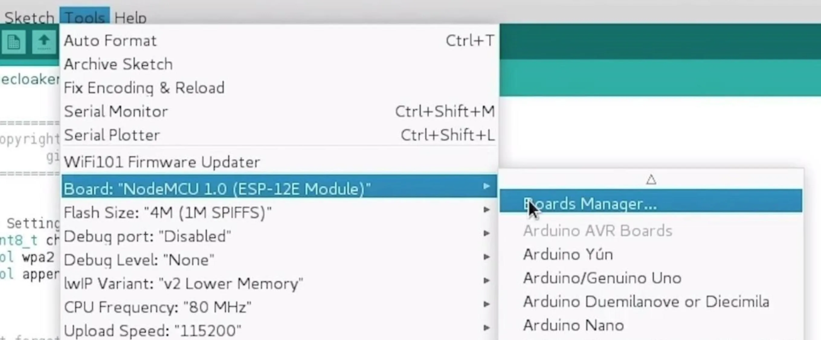
http://arduino.esp8266.com/stable/package_esp8266com_index.jsonNext, you'll need to add the NodeMCU to the Boards Manager. To do this, you'll need to click on "Tools," then hover over the "Board" section to see the drop-down list of supported boards. At the top, click "Boards Manager" to open the window that will allow us to add more boards.
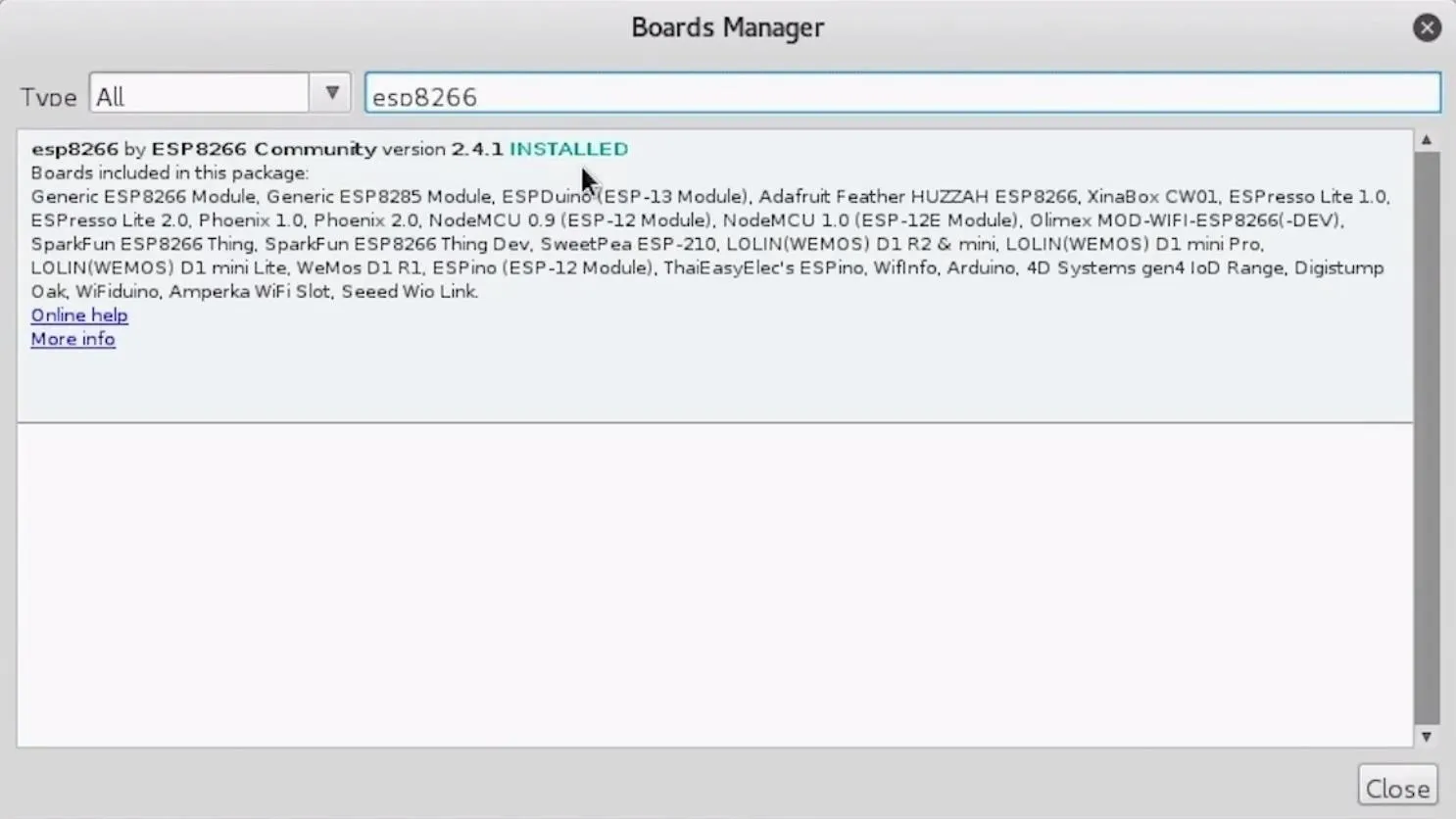
When the Boards Manager window opens, type "esp8266" into the search bar. Select "esp8266" by "ESP8266 Community," and "Install" it to add support for the D1 Mini, NodeMCU, or another ESP8266 device. Click "Close" to finish here.
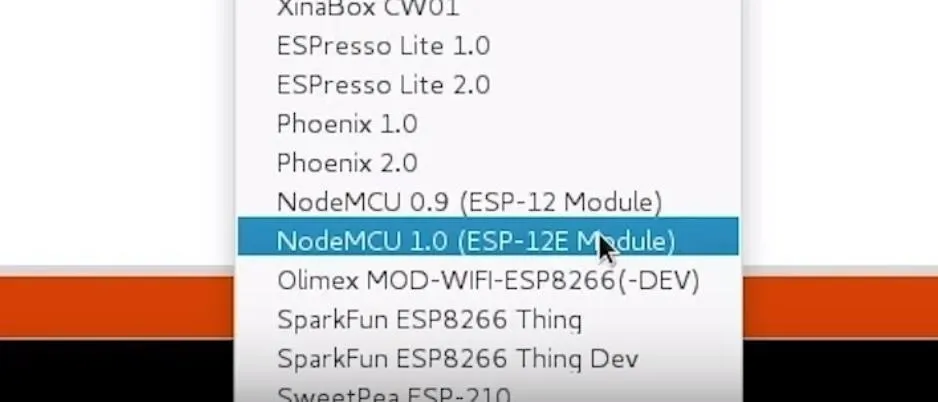
Once this is done, you should be ready to program your ESP8266-based board. Plug your D1 Mini, NodeMCU, or similar microcontroller into your computer with the Micro-USB cable. When you click on "Tools," you should see the correct device auto-selected. If not, hover over "Boards," then select either "WeMod D1 RS & mini" or "NodeMCU 1.0 (ESP-12E Module), depending on the board you have.
If you're using a bad cable, the port may not show up, so if you don't see anything after you've completed the other steps, try another cable first.
Download the Example Code
In the code box below is the complete code to control the Wi-Fi relay. It's code adapted from examples on the aRest GitHub. While you won't be able to find the exact code below on its GitHub, you can find it on skickar's GitHub aside from shown below.
/*
  This a simple example of the aREST Library for the ESP8266 WiFi chip.
  This example illustrate the cloud part of aREST that makes the board accessible from anywhere
  See the README file for more details.

  Written in 2015 by Marco Schwartz under a GPL license and forked by Skickar
*/

// Import required libraries
#include <ESP8266WiFi.h>
#include <PubSubClient.h>
#include <aREST.h>

// Clients
WiFiClient espClient;
PubSubClient client(espClient);

// Create aREST instance
aREST rest = aREST(client);

// Unique ID to identify the device for cloud.arest.io
char* device_id = "unique_device_id";

// WiFi parameters
const char* ssid = "NetworkName";
const char* password = "Password";

// Variables to be exposed to the API
int temperature;
int humidity;
String local_ip = "";

// The port to listen for incoming TCP connections
#define LISTEN_PORT           80

// Create an instance of the server
WiFiServer server(LISTEN_PORT);

// Functions
void callback(char* topic, byte* payload, unsigned int length);

void setup(void)
{
  // Start Serial
  Serial.begin(115200);

  // Set callback
  client.setCallback(callback);

  // Init variables and expose them to REST API
  temperature = 24;
  humidity = 40;
  rest.variable("temperature", &temperature);
  rest.variable("humidity", &humidity);
  rest.variable("local_ip", &local_ip);

  // Give name & ID to the device (ID should be 6 characters long)
  rest.set_id(device_id);
  rest.set_name("esp8266");

  // Connect to WiFi
  WiFi.begin(ssid, password);
  while (WiFi.status() != WL_CONNECTED) {
    delay(500);
    Serial.print(".");
  }
  Serial.println("");
  Serial.println("WiFi connected");

  // Start the server
  server.begin();
  Serial.println("Local server started on IP:");

  // Print the IP address
  Serial.println(WiFi.localIP());
  local_ip = ipToString(WiFi.localIP());

}

void loop() {

  // Connect to the cloud
  rest.handle(client);

  // Handle Local aREST calls
  WiFiClient clientLocal = server.available();
  if (!clientLocal) {
    return;
  }
  while(!clientLocal.available()){
    delay(1);
  }
  rest.handle(clientLocal);

}

// Handles message arrived on subscribed topic(s)
void callback(char* topic, byte* payload, unsigned int length) {

  rest.handle_callback(client, topic, payload, length);

}

// Convert IP address to String
String ipToString(IPAddress address)
{
  return String(address[0]) + "." +
    String(address[1]) + "." +
    String(address[2]) + "." +
    String(address[3]);
}
This will create an aRest server on your ESP8266 device, waiting for HTTP commands on port 80 at the IP address assigned by the router after connecting to your Wi-Fi network. In addition, the code will output the IP address via the serial connection, allowing you to easily find it on the network.
Copy and paste this code into a new Arduino sketch ("File," then "New"), and select whichever board you are using. Next, create a folder with the name you want to save the program, and then save the sketch into that folder. Arduino won't be able to work with the sketch until you put it in a folder of the same name.
Now, there's only one thing you need to modify to get the script working.
Modify the Code with Your Wi-Fi Credentials
Take a look at the part of the code that looks like this.
// WiFi parameters
const char* ssid = "NetworkName";
const char* password = "Password";
Modify this to replace "NetworkName" and "Password" with the name and password of your Wi-Fi network. Once this is done, the code should allow the ESP8266 device to connect to the Wi-Fi network and allow you to send it commands.
Wire the Relay & the Esp8266 Board
Now, place your D1 Mini or NodeMCU onto your breadboard. We'll need to make a few connections to get everything working.
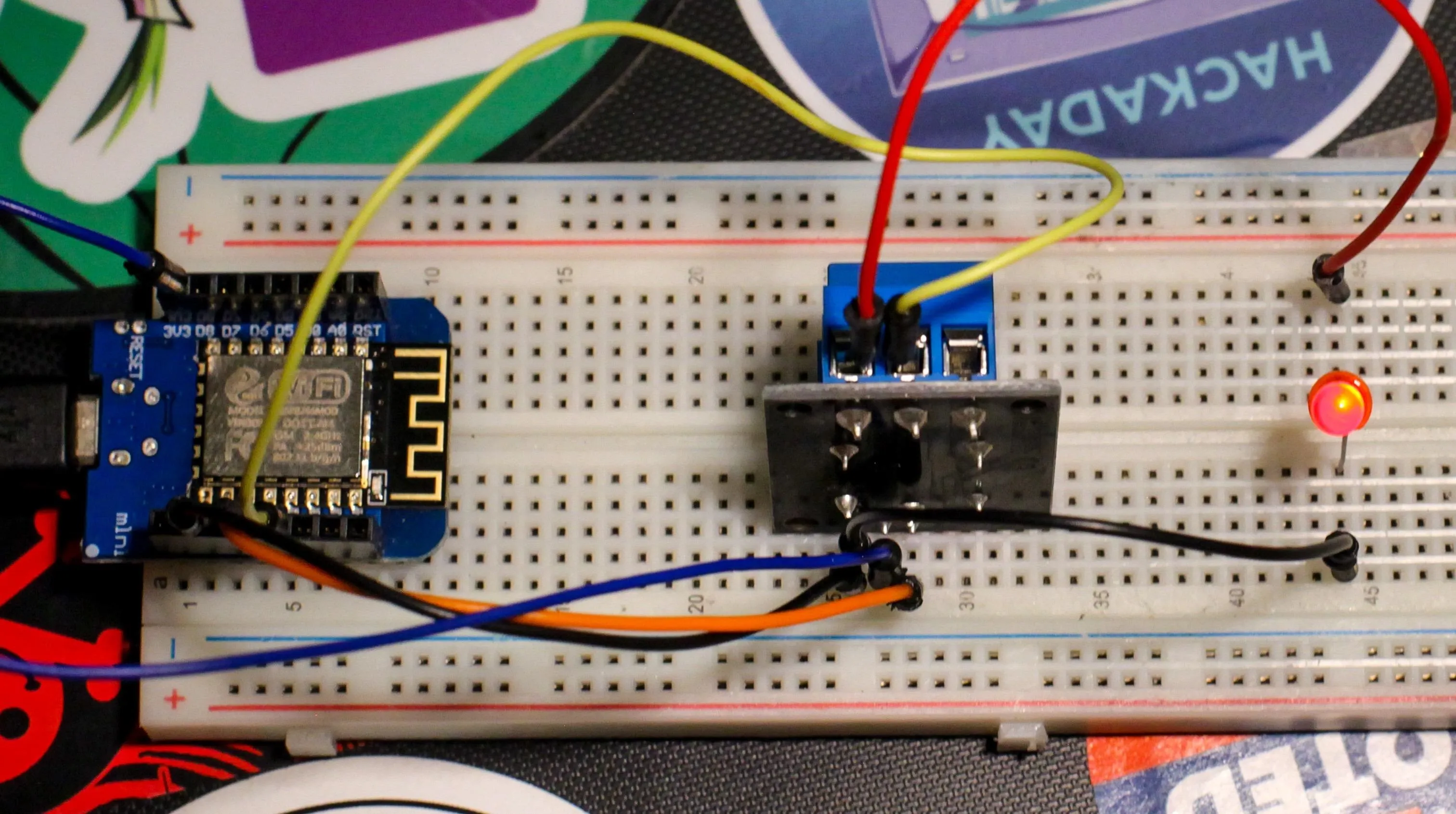
To power the relay, we'll connect the ground pin of the ESP8266's board to the ground pin of the relay, shown below with a black wire connecting the two. Also, the 3.3-volt pin of the ESP8266's board to the positive pin of the relay, shown below with a blue wire. To control the relay switching on and off, we'll connect pin D2 to the signal pin of the relay, shown below in orange.
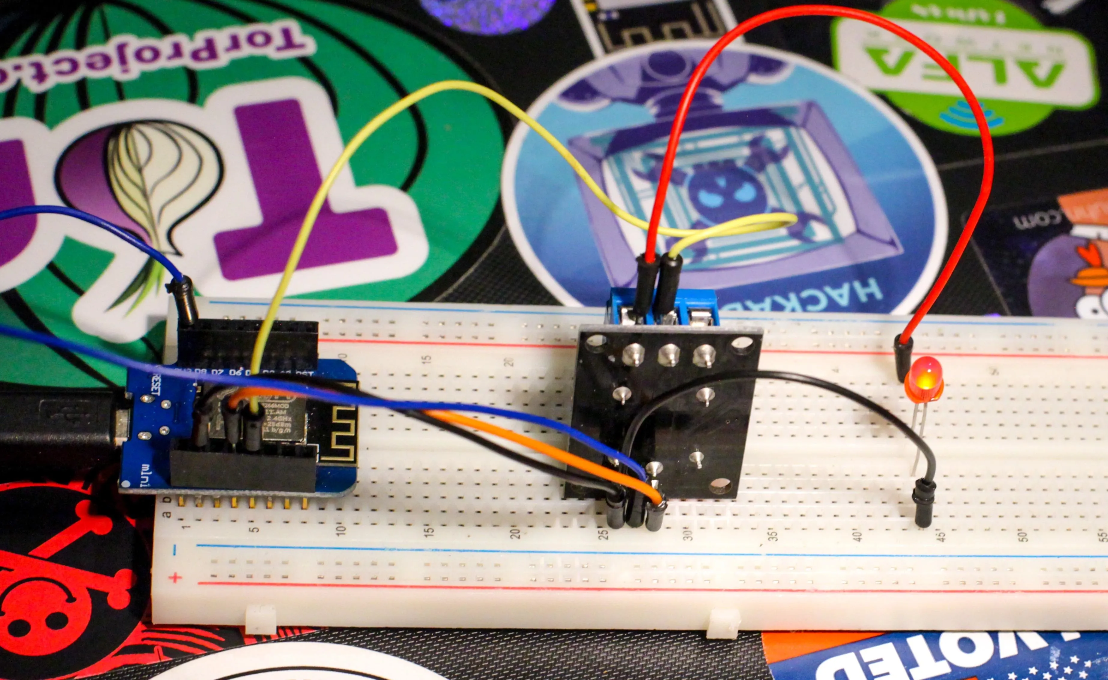
Kody/Null Byte
Now that we can control the switch, let's make a simple circuit. We can attach something like a lamp or lights here as well, but we want to keep this demo simple. We'll connect pin D3 of the ESP8266 to the center, or common terminal of the relay, seen below with a yellow wire.
If the terminals are facing up and the writing on top of the relay is facing towards you, the terminal to the right of center should be the "normally closed" terminal. Connect this "normally closed" terminal to an LED, seen below with a red wire, and then connect the other side of the LED to the open pin you left next to ground, shown below with a black wire.
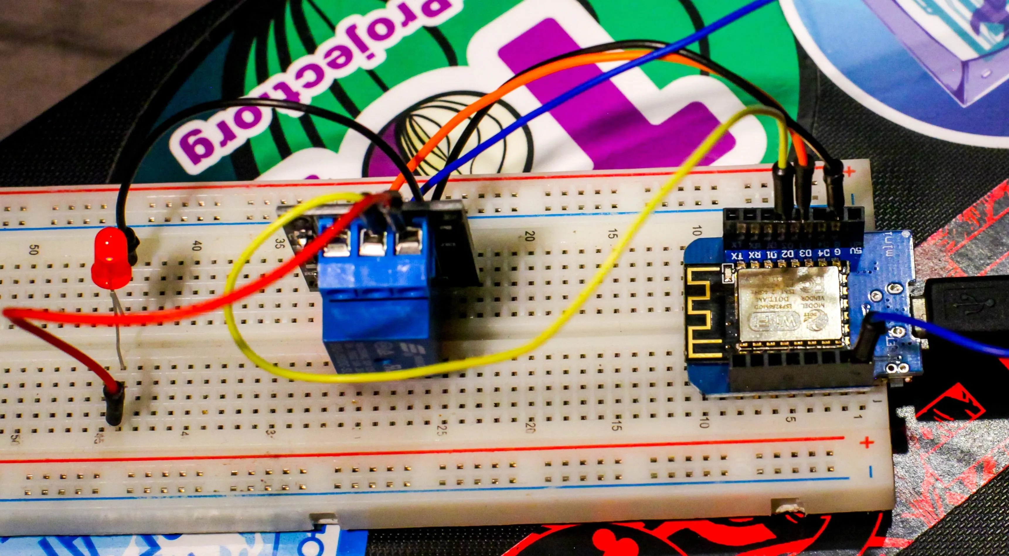
Kody/Null Byte
Now, when the signal from D2 turns on the relay, power from D3 will flow to the LED and back to the ground pin on the ESP8266. With everything wired, it's time to send our code to the device.
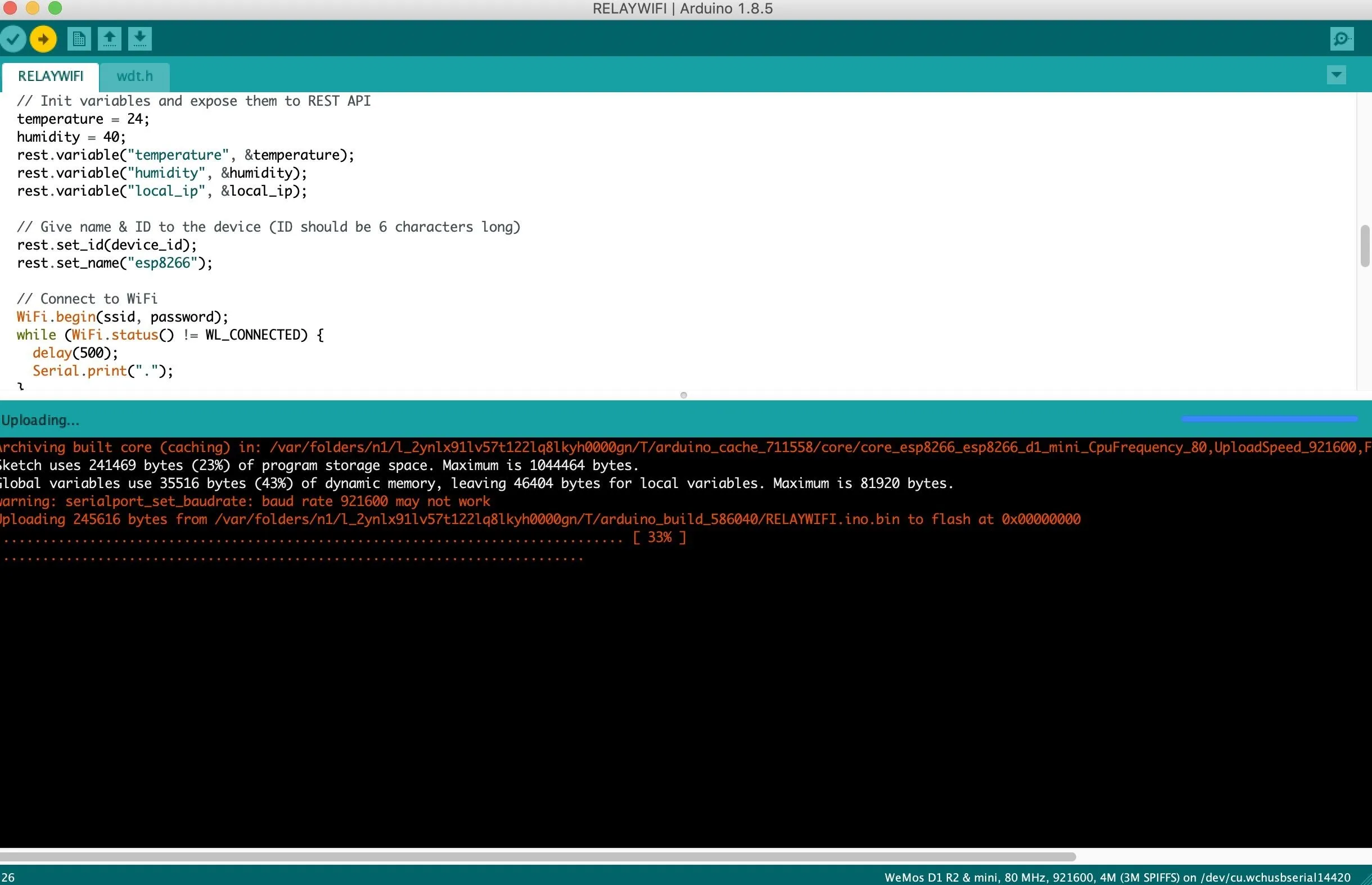
Push the Code & Power the Device
Connect the ESP8266 board with a Micro-USB cable, and make sure you select the correct board and port in Arduino IDE. Click the check button to verify, and if the code compiles successfully, click the arrow button to send the code to the ESP8266.
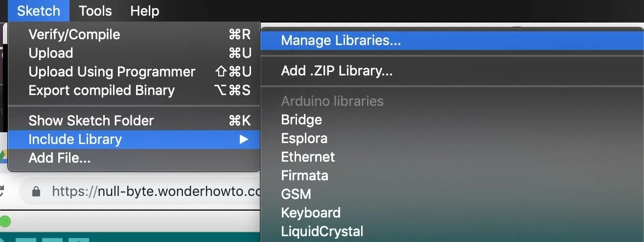
If you get any warnings about a library not being found, click on "Sketch," then "Include Library," and "Manage Libraries." This should open up the library search, where you can type in any library Arduino says is missing. Once you install the proper library, the code should compile and be able to be sent to the ESP8266.
With all this done, your ESP8266 should connect to the Wi-Fi network and be ready to accept commands. Keep it connected, because next we'll be finding where to send the commands.
Get the IP Address from Serial
Now that we've pushed the code, let's take a look at how things are going on the serial monitor. To access this, click on "Tools," then "Serial Monitor." Set the baud rate to 115200, and you should see a message similar to what's seen in the below screenshot if your device connects to Wi-Fi successfully.
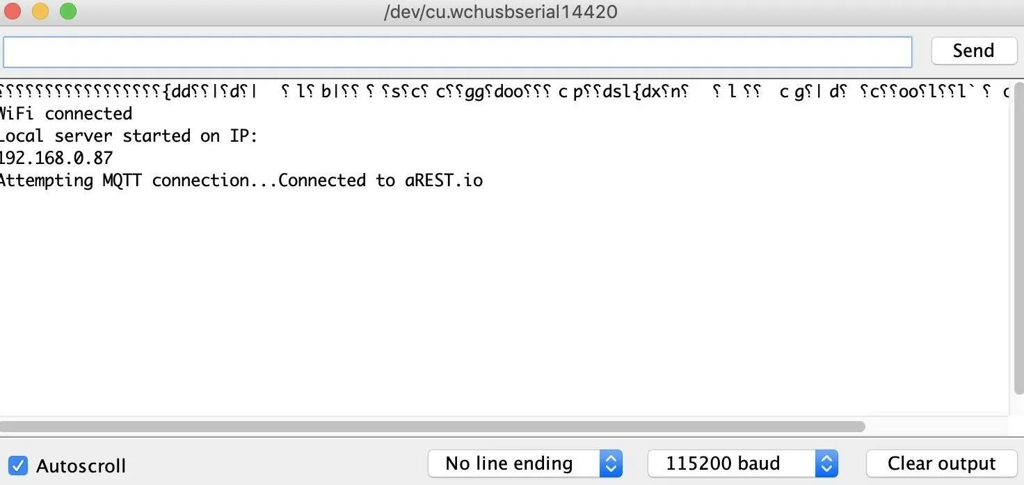
Now that we have the IP address, 192.168.0.87 in our example, we can start issuing commands to turn on the pins to activate the relay.
Arm the Output Pins
Once the ESP8266 is connected to Wi-Fi, connect to the same network on any device and open a browser window. Type the following command, with the IP address changed to match the one your ESP8266 has been given by the network.
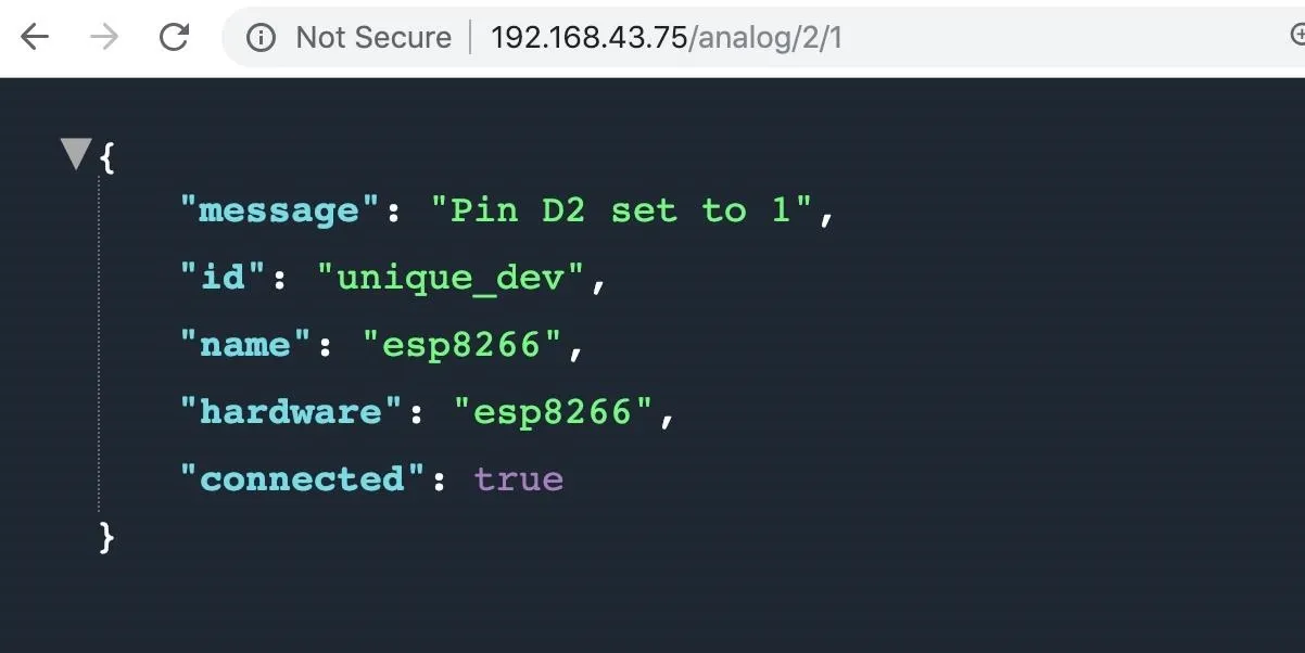
http://192.168.0.87/analog/2/1What is this doing? We are formatting an HTTP request for the device listening at 192.168.0.87, telling it we're sending an analog request to pin number 2 to set an analog value of 2 out of a maximum of 255. This will turn the power on to a low level and set the pin to output mode.
Doing this arms the pin so we can send it digital requests, which will turn the pin all the way on or all the way off. We should get a response like below.
Now, let's set the pin value to 20 so we can tell when the light turns on. Type the following into a browser window, swapping the IP address for the one belonging to your device.
http://192.168.0.87/analog/2/20The light should not turn on, but if it does, it's because you connected the "normally connected" terminal instead of the "normally disconnected" one. Now, let's arm the relay. This time, we'll send an analog signal to pin D3, which controls the relay.
http://192.168.0.87/analog/3/1We should see a response like this.
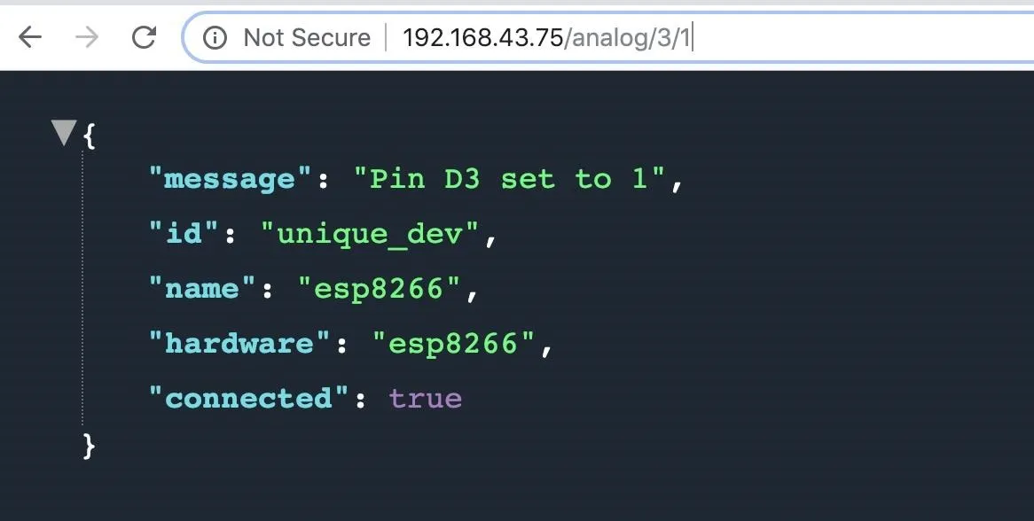
With this, the relay should be ready to switch the power we just turned on from pin D2 to the LED with one final command.
Fire the Relay from a Web Browser
Alright, the moment of truth! Let's send a digital, rather than analog, signal to the relay via pin D3 to turn it all the way on. This should trip the relay, making a clicking sound when the magnet completes the connection. Your LED should turn on, because the power from the D2 pin is now flowing through the relay and through it.
http://192.168.0.87/digital/3/1If you would prefer to stick with analog signals, sending an analog value of 255 will do the same thing, but for switching a relay on or off, a digital signal tends to be more simple.
A Wi-Fi Relay Lets You Control Power to Anything
The uses for a wirelessly controlled switch range from simple home automation to remotely cut the power to a critical computer at a key moment. While Wi-Fi jamming can interfere with these requests, the ability to rapildy set up remotely operated relays anywhere Wi-Fi is availible is a useful ability for any hacker. If access to your device from anywhere with internet access is more your style, aRest offers a dashboard to manage connected devices and automate sending commands across the internet.
While there is a limited amount of 100 free "events," or commands sent to your remote device over the internet, it's a great way to get started controlling a device you make from anywhere. Whether you want to use your relay to turn on your lights when your ESP8266 detects your phone is home, or to activate your secret Raspberry Pi hacking computer at the right moment, a relay gives you a cheap and flexible way to get started.
I hope you enjoyed this guide to controlling an electrical relay with an ESP8266 device over Wi-Fi! If you have any questions about this tutorial on connecting relays to the internet or you have a comment, feel free to reach me below in the comments or on Twitter @KodyKinzie.
- Follow Null Byte on Twitter, Flipboard, and YouTube
- Sign up for Null Byte's weekly newsletter
- Follow WonderHowTo on Facebook, Twitter, Pinterest, and Flipboard
Cover photo and screenshots by Kody/Null Byte


Comments
Be the first, drop a comment!