


Hackers and makers are often grouped under the same label. While hackers draw on computer science skills to write programs and find bugs, makers use electrical engineering to create hardware prototypes from microprocessor boards like the Arduino. We'll exercise both sets of skills to program a $6 NodeMCU to display the status of a Wi-Fi link via an LED, allowing us to monitor for jamming attacks.
While it's easy to launch attacks against Wi-Fi, detecting most attacks is relatively straightforward as well. Under normal circumstances, IoT devices can easily connect to a Wi-Fi network and perform useful functions. During a jamming attack, devices like smart speakers or connected Wi-Fi cameras are most vulnerable, as they lack a backup Ethernet link.
To spot such attacks, we can leverage a low-cost IoT device like a NodeMCU to act as a "canary in a coal mine" to warn us if connecting to a particular Wi-Fi network becomes impossible. Rather than checking for upstream connectivity, we'll program a simple detector that tries to connect to a monitored Wi-Fi network and changes an LED indicator to let us know if a standard connection is not possible.
Designing the Detector
The first step of our project is to decide what our hardware prototype is supposed to do. Because most Wi-Fi-related attacks abuse management frames to make a standard connection impossible, checking the status of the Wi-Fi link of an IoT device is a way we can test the overall ability of devices to connect. To keep things simple on our first project, we will be creating a link monitor focusing on checking the ability of a Wi-Fi device to maintain a regular connection to a network. If it cannot, we will generate an alert to warn that there is a problem with the network.
Because we are not attempting to connect and check network connectivity, there are a few limitations to this tactic. First, we will not be alerted (or get false positives) if the router isn't able to connect to the internet, but the Wi-Fi link between the router and the detector is okay.
Second, we are not looking for the telltale signs of deauthentication and disassociation frames; While we will cover this in a future build, the design we will make is more straightforward and will also be triggered by more subtle jamming attacks.
- Don't Miss: How to Use MDK3 for Advanced Wi-Fi Jamming
Of course, if an attacker filters their jamming attacks to attack only other devices on the network and leaves the "canary" alone, then the detector will always have a valid Wi-Fi link and continue to signal the link is okay even if other devices cannot connect.
In a future build, we will create a deauthentication and disassociation packet detector that will be able to detect common deauth attacks in the area. For now, we will start our journey as a maker with a more simple design to understand how IoT programming works. We'll start by looking at the underlying hardware.
The ESP8266 Chip
The ESP8266 Wi-FI radio chip has been well-known among makers for its intriguing combination of relatively powerful, hackable hardware and a low price point. Makers began noticing and documenting this chip, allowing for the eventual inclusion of support for the ESP8266 in Arduino IDE. Simple Arduino-like devices using this Wi-Fi radio can be easily programmed to use Wi-Fi to do anything a maker can imagine. From this chip, a few popular types of firmware emerged, including the NodeMCU and Arduino ESP8266 Core.
The NodeMCU
One Arduino-like device that has become popular with makers developing prototypes is the NodeMCU devkit 1.0. This inexpensive board, which I've seen go for anywhere between $5 and $9 each unit, is based around the ESP8266. It can be programmed in a variety of well-documented languages, like Arduino, Lua, and MicroPython, allowing virtually anyone to get started creating Wi-Fi-connected IoT devices using it, a breadboard, and any number of other electronics to be controlled via Wi-Fi. By just plugging a NodeMCU into a breadboard, a beginner can learn to control and blink LED lights of different color combinations in only a few minutes.
When a programmer writes their first program, it's traditional to write "Hello world" as the first output. In the maker community, the equivalent right of passage is to make an LED blink. For our prototype, we'll need the NodeMCU to tell us if it's no longer able to connect normally, meaning we'll need some indicator to let us know if there is trouble with the connection ability. To do this, we can use the onboard LED on the NodeMCU, which is blue and turns on and off. Alternatively, we could use a three-color RGB LED to give us some more options for our warning display.
In this guide, we will be using a four-pin RGB LED to blink blue when trying to find a connection, green when the connection is normal, and red when the connection is being interfered with or the network is taken down.
Parts Needed for This Guide
I've already laid out the parts needed for this guide above, but to make it super clear, here's what I ended up using:
- ESP8266 NodeMCU CP2102 Wi-Fi Internet Development Board Wireless Module (Less than $6 per unit.)
- Solderless Breadboard Kit with Jumper Wires (Around $11, but you can probably find a single breadboard with a few jumpers for less.)
- Tricolor RGB LED (Around $9 for a bunch, but you can get just one at a local store for super cheap.)
- Micro USB Cable (You probably already have one of these.)
- Resistors (Optional, if you want the LED to last longer.)
Set Up the Arduino IDE
There are several languages in which you can program a NodeMCU, and depending on your background, you can use whichever you are most comfortable with. In this guide, we will use the free and cross-platform Arduino IDE, which will allow us to quickly prototype what we need. Arduino IDE (the IDE stands for "integrated development environment") allows you to quickly write and upload scripts to Arduino-like microcontroller devices.
You can download the Arduino IDE from the official website. Once you've downloaded and installed it, you'll need to click on the "Arduino" drop-down menu, then select "Preferences" from the menu that appears.
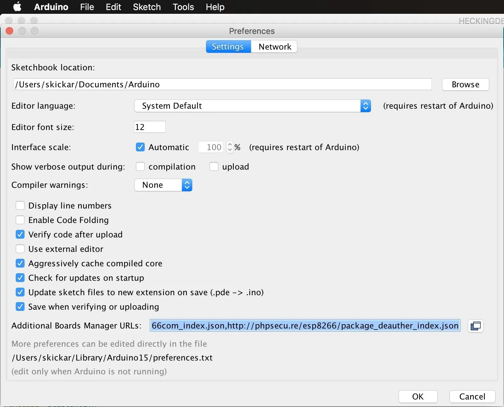
In the "Preferences" menu that opens, paste the following URL into the "Additional Boards Manager URLs" field. Once that's complete, click "OK" to close the menu.
http://arduino.esp8266.com/stable/package_esp8266com_index.jsonConfigure the Arduino IDE for the ESP8266
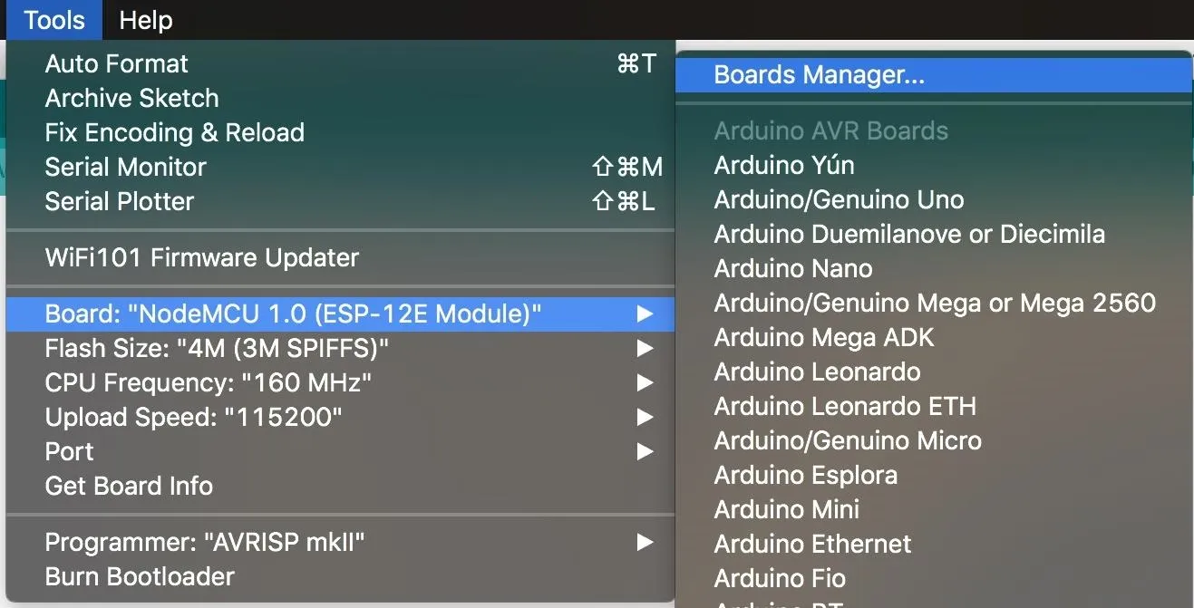
Next, you'll need to add the NodeMCU to the Boards Manager. To do this, you'll need to click on "Tools," then hover over the "Board" section to see the drop-down list of supported boards. At the top, click "Boards Manager" to open the window that will allow us to add more boards.
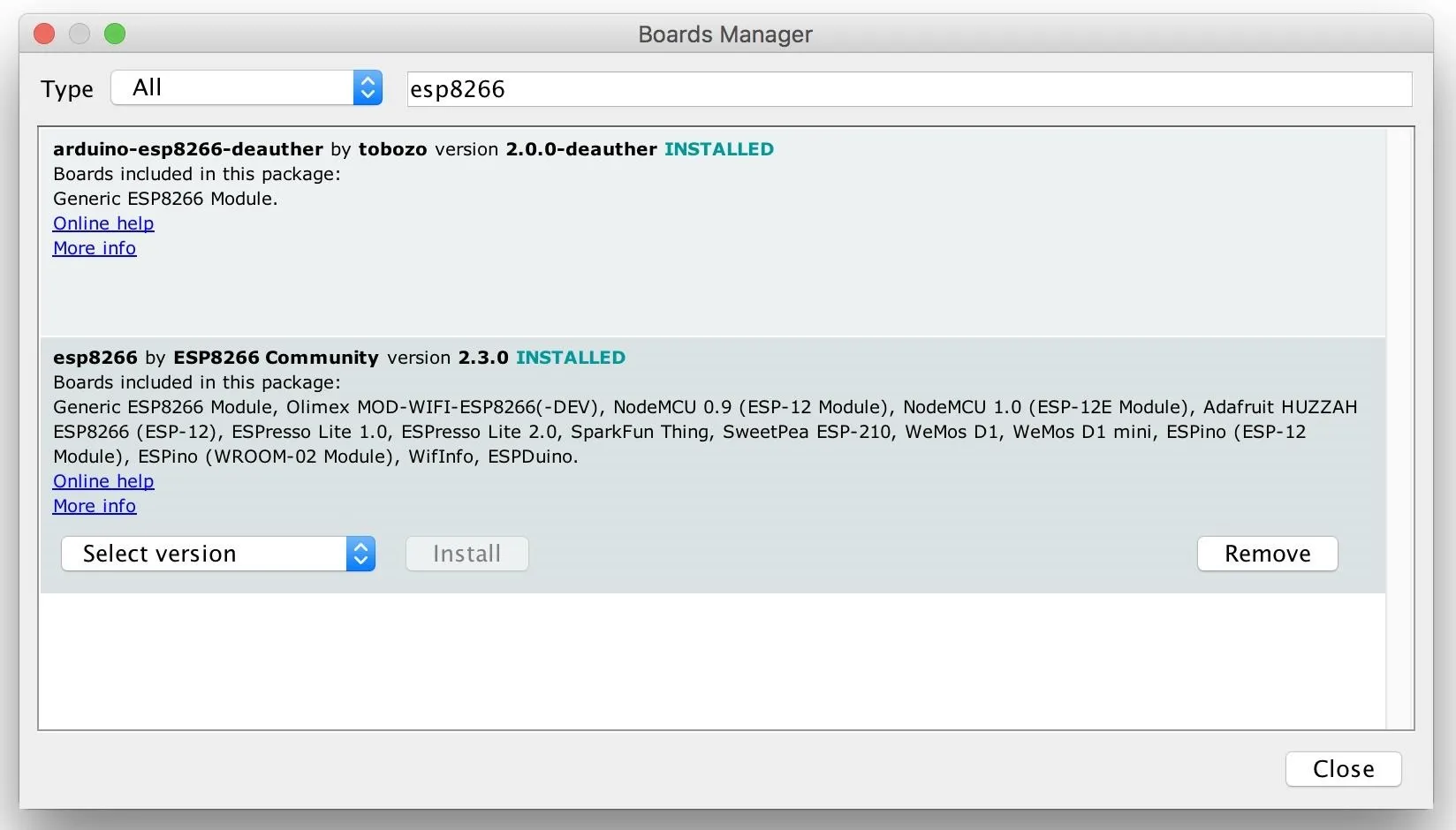
When the Boards Manager window opens, type "esp8266" into the search bar. Select "esp8266" by "ESP8266 Community," and install it to add support for the NodeMCU to your Arduino IDE.
Once this is done, you should be ready to program your NodeMCU. Plug your NodeMCU into your breadboard, and your NodeMCU into the computer. When you click on "Tools," you should see the correct port auto-selected. Select the "NodeMCU 1.0" as shown in the image below. If you're using a bad cable, the port may not show up, so if you don't see anything after you've completed the other steps, try another cable first.
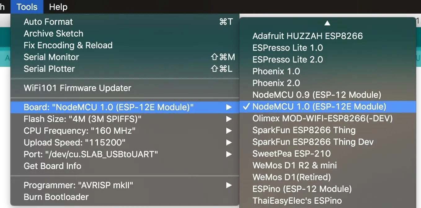
There are two main buttons at the top. One compiles and checks our code for mistakes before uploading it, and the second icon that looks like an arrow pushes the code to the NodeMCU.
Wire the NodeMCU to an LED
Our first challenge will be getting the NodeMCU to blink a particular color when we tell it to, allowing us to use an RGB LED to indicate the status of something we can't see — the Wi-Fi connection. Let's write some code to blink an LED!
The kind of RGB LED we'll be using is very simple to control. We have a ground pin that's longer than the other pins, and then one pin for each color, red, green, and blue.
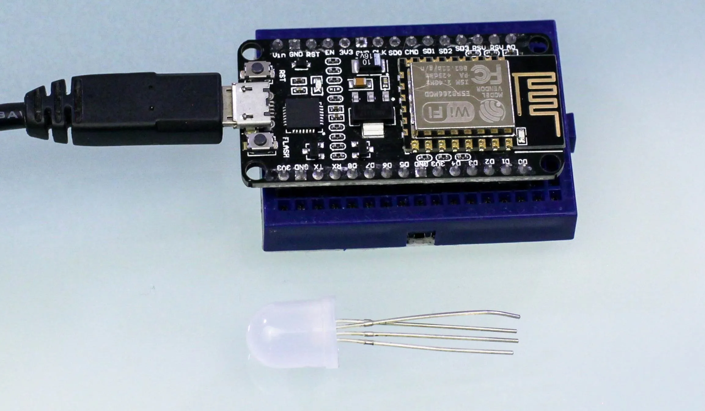
Looking at the top of the NodeMCU, you'll notice the pins are labeled. The D0 through D8 pins we can program to control an LED, while the GND (ground) pin lets us connect the ground pin of the LED, completing the circuit and allowing the LED to light up. We will plug the RGB LED in next to the GND, D5, D6, and D7 pins on the NodeMCU, with the longer pin connected to the GND position. We'll need to map each pin to a color, so that in our program, when we tell a pin to turn on, it will turn on that particular color.
To understand how a breadboard is used to connect pins, take a look at this image of the back side of a full-sized breadboard. Here, you can see that the rows in the center are connected, while the columns at each edge are connected for applying power and ground.
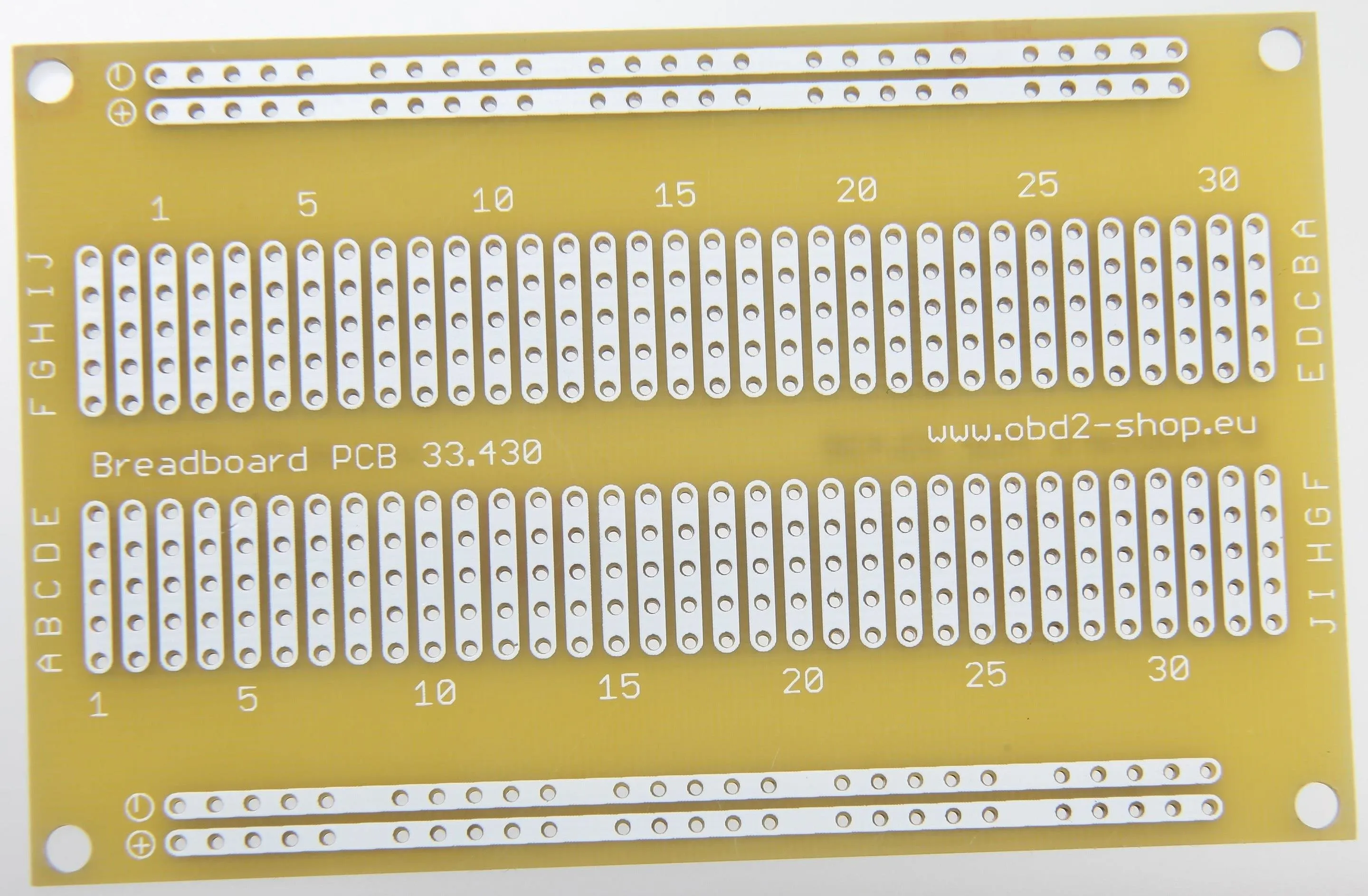
The connections of a breadboard.
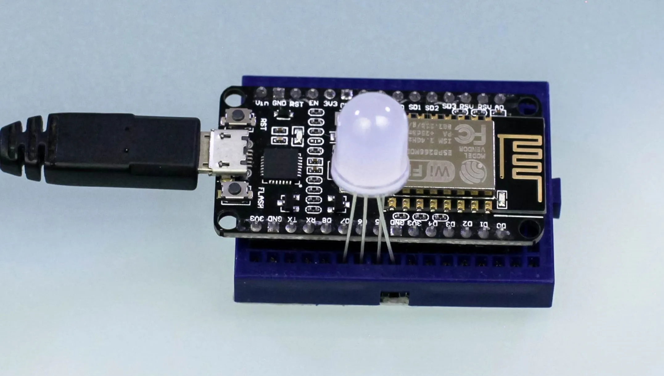
We will plug the LED's pins into the breadboard next to the corresponding pins on the NodeMCU, as seen in the picture below with our mini-breadboard. This smaller breadboard lacks the columns seen on the sides of the full breadboard pictured above.
If you have resistors, you can extend the life or your LED's by putting them in between the pin and the LED. While not strictly necessary, connecting the LED without a resistor isn't technically the best way to do this as it can burn out the LED eventually, but it is by far the fastest way to get started.
If you can spare the resistors, the space on your breadboard, and some wires for the red, green, and blue connections, you can assemble the board as seen below. Instead of plugging in the LED directly to the pins, use a resistor to sit in-between the voltage from each pin and the LED, except for the ground pin. After doing so, you can connect directly to the LED's ground pin without a resistor.
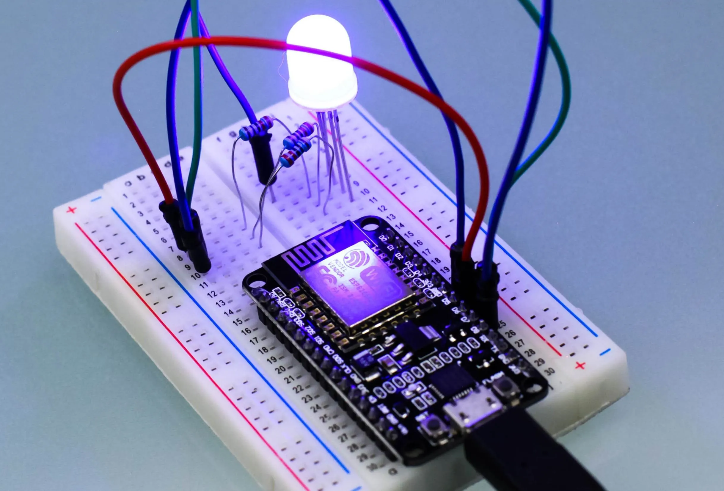
With the LED plugged into either configuration, it's time to flash some code and get the LEDs to light up.
Write a Simple Program for the NodeMCU
To test the connections and set up our colors, we'll use a basic program to blink the LED different colors. You can see the code we'll use below.
int highTime = 1000, lowTime = 100; // First, we define how long the light should be on (highTime) and how long the light should be off (lowTime) per blink in miliseconds (1000 = 1 sec)

void red() { // Next, we create a function for the color red. You can expariment or swap these after testing them. For now, we will map pin D5 to our function "red"
      digitalWrite(D5, HIGH), delay(highTime), digitalWrite(D5, LOW), delay(lowTime);
}
void green() { // We will repeat this process for the color green. As a note, these are "void" functions because unlike normal functions they don't return any data, they just do something.
      digitalWrite(D6, HIGH), delay(highTime), digitalWrite(D6, LOW), delay(lowTime);
}
void blue() { // Finally, we create a function for the color blue as well.
      digitalWrite(D7, HIGH), delay(highTime), digitalWrite(D7, LOW), delay(lowTime);
}
void setup() { // This runs first to set up for our program, and only runs once. In this step, we will tun on the pins.
  pinMode(D5, OUTPUT), pinMode(D6, OUTPUT), pinMode(D7, OUTPUT); // Here we turn on pins D5, D6, and D7 for output.
      }

void loop() { // This loop will run over and over.
     red(),green(),blue(); // Here, we call our functions, red(), green(), and blue() one after another to test our blinking LED's.
     delay(100); // The last thing we do is add a delay to create a pause between the blinking of our lights, in miliseconds.
}
Let's break this down to understand what it's doing.
In a basic Arduino program, there are a few main elements. First, we have variables and libraries we're including; This will control the resulting code by allowing us to change things like how long the LEDs blink for.
We'll start by creating two variables to determine how long a blink should be, by defining how long to turn on and off the LED each time we activate it. We'll create the variable highTime to store how long in milliseconds to leave the LED on, and lowTime for how long to leave the LED off per blink.
int highTime = 1000, lowTime = 100; // First, we define how long the light should be on (highTime) and how long the light should be off (lowTime) per blink in miliseconds (1000 = 1 sec)Next, we'll create and define three functions we can call each time we want to blink the LED a particular color. These will need to be "void" functions because unlike a regular function that returns data, these functions do something without returning any result.
To blink the red LED, we create a red() function, and then inside the curly braces, use the built-in digitalWrite() function to turn a pin off and on.
To use the digitalWrite() function, you need to include the pin you want to call and the power setting to change the pin to between the parenthesis. If I want to supply power to pin D5, I would type digitalWrite(D5, HIGH), and to turn the same pin off, digitalWrite(D5, LOW); This would turn on and off whichever color LED pin is attached to D5.
With this logic, we can use the code below to map each color function to the correct pin, so that calling the function first turns on, and then turns off the LED color connected to that pin. If your colors don't match the pin number first time, you can switch the pin numbers in your code to match the way you wired it.
void red() { // Next, we create a function for the color red. You can expariment or swap these after testing them. For now, we will map pin D5 to our function "red"
      digitalWrite(D5, HIGH), delay(highTime), digitalWrite(D5, LOW), delay(lowTime);
}
void green() { // We will repeat this process for the color green. As a note, these are "void" functions because unlike normal functions they don't return any data, they just do something.
      digitalWrite(D6, HIGH), delay(highTime), digitalWrite(D6, LOW), delay(lowTime);
}
void blue() { // Finally, we create a function for the color blue as well.
      digitalWrite(D7, HIGH), delay(highTime), digitalWrite(D7, LOW), delay(lowTime);
}
Next, we'll need to address the part of the program that only runs once, called the setup function; This is mandatory in Arduino programs. In ours, we will use the built-in pinMode(pin, mode) function to activate the pins we will be using, telling the function which pin to call and what mode to set on it. To set pins D5, D6, and D7 to OUTPUTmode, we will use the code below.
void setup() {
  pinMode(D5, OUTPUT), pinMode(D6, OUTPUT), pinMode(D7, OUTPUT);
      }
Finally, we have the loop section; This will run over and over again. In this section, we will call each of the color functions we wrote, and then add a delay at the end of each cycle in milliseconds; This should result in the NodeMCU lighting up each color in the LED one after the other.
void loop() {
     red(),green(),blue();
     delay(100);
}
Flash the Simple Program to the NodeMCU
Now, we're ready to test! Connect your NodeMCU via a Micro-USB cable to your computer, if not already done, and make sure the pins of the LED are connected to the GRD, D5, D6, and D7 pins on the breadboard.
Copy and paste the script at the start of Step 4 into a blank Arduino IDE sketch, and click on the "Upload" button on the top left that looks like an arrow, and the program will be written to the NodeMCU as seen below.
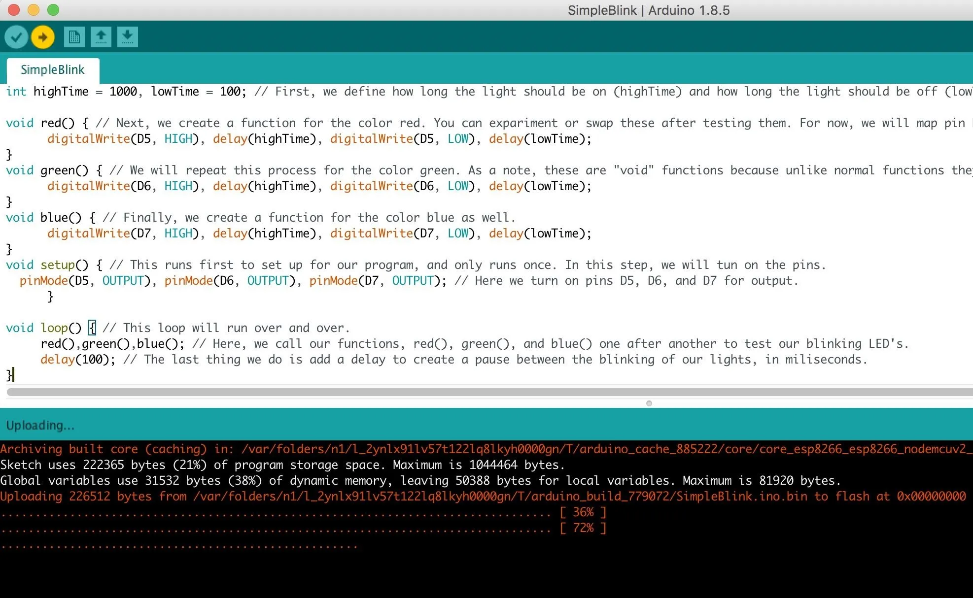
After the program is finished loading, your NodeMCU should power on and begin blinking through the three colors in the order you programmed it to.
If you'd like to download my script to blink the lights directly, you can run the command below to download it from my GitHub repository. You can open the .INO file in the resulting folder in Arduino IDE to see the code.
git clone https://gitlab.com/skickar/NodeMCUWiFiLinkMonitor.git
cd NodeMCUWiFiLinkMonitor
ls
Write the Wi-Fi Checking Code
If the indicator light test worked, then we're ready to move on to our functional code. We'll need to add a few more variables to the beginning in order to make the Wi-Fi monitor work. We'll use the LED color functions to show three conditions.
In the first condition, the NodeMCU cannot ever connect to the access point (AP) successfully. This means that the password may be wrong, the AP may be down, or something may be wrong with the SSID and password. We'll make the light turn blue in this condition to warn us that way may need to troubleshoot our code.
To make this work, we'll create a variable called "connectSuccess" and set the value to zero. This variable will keep track of whether we do manage to successfully connect to the target network. Once the value of connectSuccess is above zero, we can tell our program to blink the red LED instead of the blue LED when the connection fails to let us know that a previously possible connection is being blocked or is otherwise unavailable.
To start, we will need to add the "ESP8266WiFi.h" library to control the Wi-Fi card to our previous code. After that, we will need to create a variable to hold the SSID and password to the network you want to join. We'll create a variable to hold the current Wi-Fi status each time we run our loop, and then add our connectSuccess variable set to zero.
const char* ssid     = "Control"; // Next, we set the name of the network to monitor.
    const char* password = "testytest"; // After that, we enter the password of the network to monitor.
    int wifiStatus; // Here, we create a variable to check the status of the Wi-Fi connection.
    int connectSuccess = 0, highTime = 100, lowtime = 100; // And now, we set a variable to count the number of times we've been able to successfully connect, and how long the LED will stay on and off for.

void red() { // Here, we will map a function called "red" to the right pin that will light up the red LED for the amount of time we defined in hightTime for how long it is lit, and lowTime for how long it is off each time we pulse a red LED.
      digitalWrite(D5, HIGH), delay(highTime), digitalWrite(D5, LOW), delay(lowtime);  // We map the red function to the D5 pin, so that each time we call red() it will pulse power on the D5 pin.
}
void green() { // We do the same with green, mapping the D6 pin to the green() function.
      digitalWrite(D6, HIGH), delay(highTime), digitalWrite(D6, LOW), delay(lowtime);
}
void blue() { // Finally, we do the same with blue, mapping it to the D7 pin.
      digitalWrite(D7, HIGH), delay(highTime), digitalWrite(D7, LOW), delay(lowtime);
      }
Now, inside the setup loop, we'll call the WiFi.begin(ssid, password) function to attempt to connect to the wireless network. We'll include everything that was present in our LED program before as well.
void setup() { // The setup function runs only once when the device starts up.
  pinMode(D5, OUTPUT), pinMode(D6, OUTPUT), pinMode(D7, OUTPUT); // In this case, we will activate the D5, D6, and D7 pins for output mode.
      WiFi.begin(ssid, password); // The last part of setup we will write is to start the Wi-Fi connection process.
      }
Next, we'll add some new logic to the loop() function.
First, we'll check the Wi-Fi status and write the result to the variable we created called wifiStatus. Next, we'll check to see if we've successfully connected previously by checking if the value of connectSuccess is more then zero. If the value is still zero, we will blink the blue LED by calling the blue() function to tell the user that we have yet to make a successful connection to the target AP.
Next, we check to see if the value of wifiStatus is equal to WL_CONNECTED. If it is, we will turn on the green LED with the green() function and increase the value of the connectSuccess counter variable by one by typing connectSuccess ++. From now on, if the connection fails, it will activate the red LED rather than the blue LED because the value of connectSuccess is more than zero.
Finally, if the value of wifiStatus is something other than WL_CONNECTED and the value of connectSuccess is not zero, we will turn on the red LED by calling the red() function. After we're done with the logic, we can add a final command to create a delay of 1 second between each check of the Wi-Fi status.
void loop() { // This loop will run over and over again, unlike the setup function, which will only run once.
      wifiStatus = WiFi.status(); // First, we'll check the status of the Wi-Fi connection and store the result in the variable we created, wifiStatus.
      if(connectSuccess == 0){ blue();} // If device is not connected and never has successfully connected, flash the blue light. This could mean the network doesn't exist, is out of range, or you misspelled the SSID or password.
      if(wifiStatus == WL_CONNECTED){ green(), connectSuccess ++;} // If the device is connected, flash the green light, and add one to the count of the "connectSuccess" variable. This way, we will know to flash the red light if we lose the connection.
      else if(connectSuccess != 0){ red(); } // If the connection is not active but we have been able to connect before, flash the red LED. That means the AP is down, a jamming attack is in progress, or a normal link is otherwise impossible.
      delay(1000); // Set a delay of one second per cycle of checking the status of the link.
}
Our final code will look like the example below.
// SIMPLE Wi-FI LINK MONITOR BY SKICKAR - Based on Henry's Bench Wi-Fi link checker
// This project has the goal to connect an ioT device to a Wi-Fi network and monitor the ability to establish a normal wireless connection.
// The project uses only three componants - A nodeMCU, a breadboard, and one RGB LED.
    #include <ESP8266WiFi.h> // First, we include the libraries we need to make this work on the ESP8266

    const char* ssid     = "Control"; // Next, we set the name of the network to monitor.
    const char* password = "testytest"; // After that, we enter the password of the network to monitor.
    int wifiStatus; // Here, we create a variable to check the status of the Wi-Fi connection.
    int connectSuccess = 0, highTime = 100, lowtime = 100; // And now, we set a variable to count the number of times we've been able to successfully connect, and how long the LED will stay on and off for.

void red() { // Here, we will map a function called "red" to the right pin that will light up the red LED for the amount of time we defined in hightTime for how long it is lit, and lowTime for how long it is off each time we pulse a red LED.
      digitalWrite(D5, HIGH), delay(highTime), digitalWrite(D5, LOW), delay(lowtime);  // We map the red function to the D5 pin, so that each time we call red() it will pulse power on the D5 pin.
}
void green() { // We do the same with green, mapping the D6 pin to the green() function.
      digitalWrite(D6, HIGH), delay(highTime), digitalWrite(D6, LOW), delay(lowtime);
}
void blue() { // Finally, we do the same with blue, mapping it to the D7 pin.
      digitalWrite(D7, HIGH), delay(highTime), digitalWrite(D7, LOW), delay(lowtime);
}
void setup() { // The setup function runs only once when the device starts up.
  pinMode(D5, OUTPUT), pinMode(D6, OUTPUT), pinMode(D7, OUTPUT); // In this case, we will activate the D5, D6, and D7 pins for output mode.
      WiFi.begin(ssid, password); // The last part of setup we will write is to start the Wi-Fi connection process.
      }

void loop() { // This loop will run over and over again, unlike the setup function, which will only run once.
      wifiStatus = WiFi.status(); // First, we'll check the status of the Wi-Fi connection and store the result in the variable we created, wifiStatus.
      if(connectSuccess == 0){ blue();} // If device is not connected and never has successfully connected, flash the blue light. This could mean the network doesn't exist, is out of range, or you misspelled the SSID or password.
      if(wifiStatus == WL_CONNECTED){ green(), connectSuccess ++;} // If the device is connected, flash the green light, and add one to the count of the "connectSuccess" variable. This way, we will know to flash the red light if we lose the connection.
      else if(connectSuccess != 0){ red(); } // If the connection is not active but we have been able to connect before, flash the red LED. That means the AP is down, a jamming attack is in progress, or a normal link is otherwise impossible.
      delay(1000); // Set a delay of one second per cycle of checking the status of the link.
}
You can also find this code in the same GitHub repo the blinking .INO file was downloaded from.
Run the Code & Testing
With this complete, upload your code to the NodeMCU in the Arduino IDE and then wait for it to finish rebooting. Now it's time to test the device.
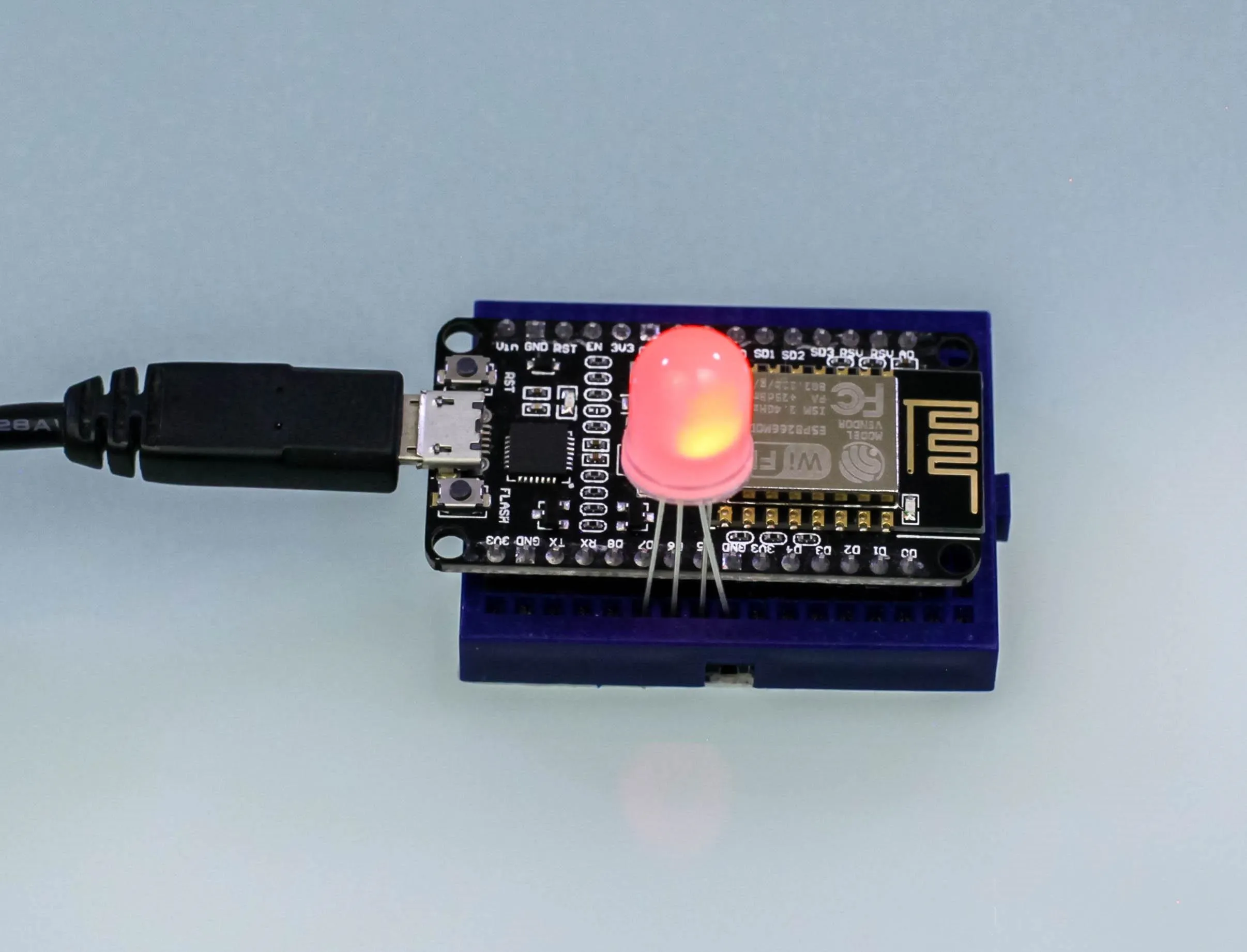
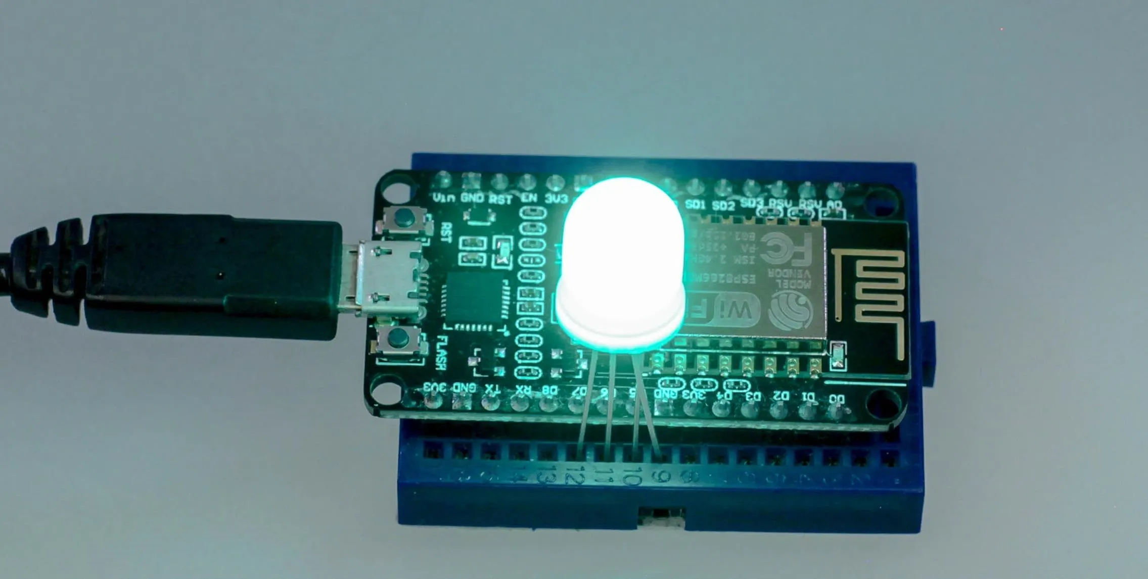
The best way to do so is to use your phone's wireless hotspot. Set the SSID and password in your program to that of your hotspot to easily test if the program works. To start, boot the NodeMCU with your hotspot off, and it should blink blue while unable to connect. When you turn on your Wi-Fi hotspot, it should blink green, and when you turn the hotspot off again, it should blink red.
If you don't have a phone with a hotspot, you can test it on your network too. Using one of our guides on MDK3 or Aireplay-ng, connect the NodeMCU to a network you have permission to test on, and attack the NodeMCU (or the channel if you have permission to) with a deauthentication or disassociation attack.
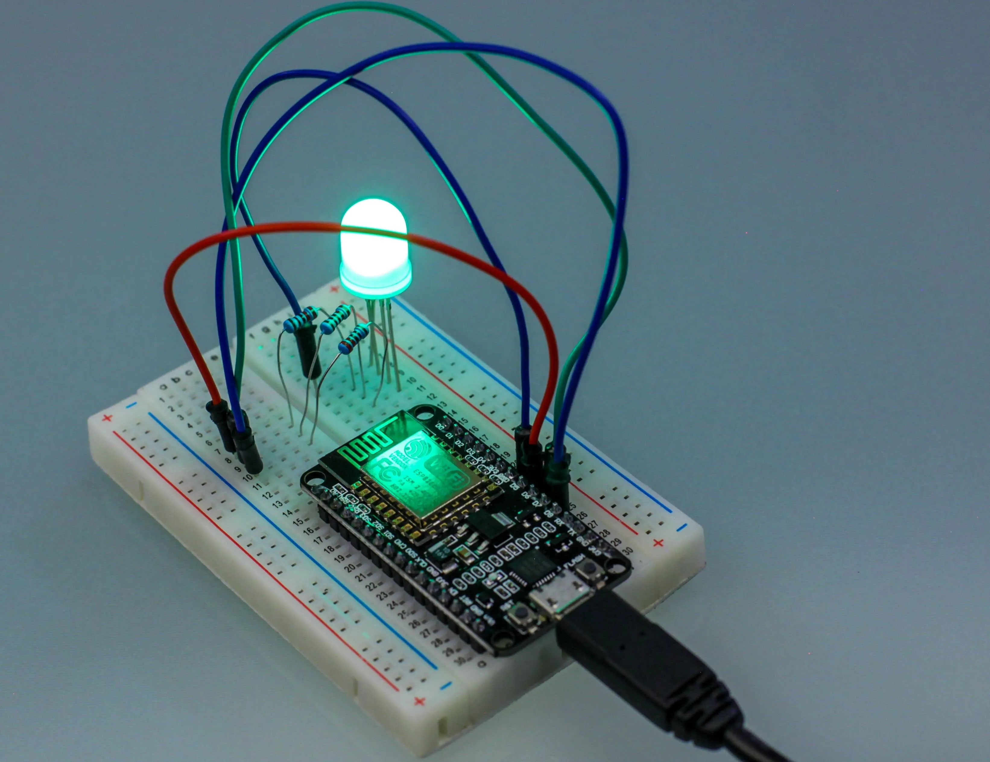
You should see the LED turn red as soon as your attack becomes effective, then turn green again when the attack subsides. You can use the NodeMCU as a "victim" device to practice jamming and deauthentication attacks with an easy LED indicator to show when you succeed.
Amazing Projects Are Possible with the ESP8266 & Arduino IDE
Armed with a low-cost board and Arduino IDE, we've created a simple code to monitor a network connection and shown how easy it is to automate a small, useful function with an IoT device. Aside from detecting attacks, the ESP8266 can also attack networks and has been used in projects ranging in variety from controlling intricate LED masks to small deauthentication packet generators like the esp8266 deauther by Spacehuhn.
With so many low-cost building blocks like the NodeMCU available that come with Wi-Fi built-in, connecting these devices to a network to do basic useful functions is simple even for a beginning maker. More advanced and creative uses of these building blocks can allow networks of targeted Wi-Fi protocol jammers to be distributed to deny coverage over a wide area, or detectors to automate Wi-Fi surveillance.
I hope you enjoyed this guide to detecting Wi-Fi jamming attacks by programming a NodeMCU in Arduino IDE. If you have any questions about this tutorial on Arduino programming or you have a comment, feel free to reach me on Twitter @KodyKinzie or comment below.
- Follow Null Byte on Twitter, Flipboard, and YouTube
- Follow WonderHowTo on Facebook, Twitter, Pinterest, and Flipboard
Cover photo and screenshots by Kody/Null Byte (unless noted otherwise)


Comments
Be the first, drop a comment!