


The USB Rubber Ducky is a well-known hacking device in the cybersecurity industry, but it needs to be preprogrammed before it can be used. That means it's not easy to issue commands to a target computer since you can't interact with it from afar after plugging it in. And if you don't know what the target computer is, you might come up empty. That's where the WiFi Duck comes in handy.
The WiFi Duck is a project created by Stefan Kremser, also known as Spacehuhn. With it, you can plug the WiFi Duck into a target computer that's exposed even for just a minute, then connect to it over Wi-Fi from another device to issue whatever payloads you have ready or can build before you have to disconnect.
The advantage is that you can connect to a slick web interface, save your own codes, and run them one by one, or write code on the fly to cause effects on the computer that you might not have intended before you knew what was on the computer. For example, if you didn't know the operating system. Or if there were other variables you couldn't account for before actually seeing the target computer.
- Don't Miss: Hack MacOS with Digispark Ducky Script Payloads
To use the Wi-Fi Duck, you need to be able to connect to it via Wi-Fi. So you can connect it to your computer and preload it with many different Ducky Script payloads. You can then connect it to a target device in the real world, connect to its network from your smartphone, then run commands you had ready or can write in real-time.
Parts Needed
If you don't want to build your own, there are boards pre-flashed with the correct WiFi Duck software, which you can grab from AliExpress, DSTIKE, or Tindie for $27 plus shipping that can run from $6 or more depending on your location. It ships from China, which might not be convenient if you live in the U.S. For faster delivery, you can get a DSTIKE WiFi Duck on Amazon for $39.99 and free shipping.
- Buy on Amazon: DSTIKE WiFi Duck USB Keyboard for $39.99
For the more adventurous type, a WiFi Duck can be built using a few microcontrollers. First, you'll need an ATmega32U4-based board such as an Arduino Leonard or a Pro Micro. This will be the board that acts as the USB keyboard for input. We used the Pro Micro listed below because a Leonard board is a little bigger, and portability is a hacker's best friend.
- Buy on Amazon: Pro Micro ATmega32U4 Module for $11.99
- Buy on Amazon: Arduino Leonard ATmega32U4 Module for $13.99
The next microcontroller needs to be either an ESP8266 or ESP8285, such as the NodeMCU or D1 Mini. This is the board that acts as the Wi-Fi access point. Designed for wearables, the ESP8285 is a smaller version of the ESP8266 with less flash memory. Again, we wanted a smaller prototype, so we went with one of the D1 Minis below.
- Buy on Amazon: D1 Mini ESP8266 Board for $8.99
- Buy on Amazon: D1 Mini ESP8285 Board for $10.99
- Buy on Amazon: NodeMCU ESP8266 Board (3 Pack) for $13.49
- Buy on Amazon: NodeMCU ESP8285 Board (2 Pack) for $11.49
Aside from that, you'll also need a breadboard to build a prototype, jumper wires, and a Micro-USB cable if you don't already have one. For the Micro-USB cable, make sure it's one that is both for charging and data transfer. It's hard to tell, but some of your old cords laying around might be charging-only, and you'll know if you can't find any of the MCUs above as a port later. You can also use an optional NeoPixel (WS2812b) or Dotstar (APA102) LED.
- Buy on Amazon: Solderless Prototype Breadboards (Various Sizes) for $8.99
- Buy on Amazon: Assorted Jumper Wires for $7.99
- Buy on Amazon: Nylon Braided Micro-USB Data Cable for $3.96
- Buy on Amazon (optional): Neopixel-Style LEDs (100 Pack) for $15.89
If you'd like to solder the two microcontrollers together, you can use one of these printed circuit board designs to make your own PCBs and solder the two components together.
- On EasyEDA: Design for D1 Mini + Pro Micro
- On EasyEDA: Design for NodeMCU + Pro Micro
Software Needed
To push all of the code to the two microcontrollers, you'll need the Arduino IDE, which works for Linux, macOS, and Windows, so make sure to install that if you don't already have it. Additionally, you will need to have an updated version of Python 3 on your system since the code we'll push to the ESP8266 won't upload correctly without it.
While we don't recommend installing any drivers since you may not need them, if you have issues later connecting to your boards and know it's not because of the Micro-USB cable, try installing the CP210x USB to UART Bridge VCP driver and/or the CH340 driver. Hopefully, one or both of those will do the trick.
Assemble the Wi-Fi Duck
To connect the ESP8266 and ATmega32U4, we'll be working with a breadboard and jumper wires. So place each MCU on the breadboard, then use jumper wires to make the following pin connections.
- D1 or GPIO 5 (ESP8266) to 3 or SCL (ATmega32U4)
- D2 or GPIO 4 (ESP8266) to 2 or SDA (ATmega32U4)
- GND (ESP8266) to GND (ATmega32U4)
- 5V (ESP8266) to RAW (ATmega32U4)
If you have a NeoPixel LED, also make these connections:
- VCC (NeoPixel) to VCC (ATmega32U4)
- GND (NeoPixel) to GND (ATmega32U4)
- DI (NeoPixel) to 7 (ATmega32U4)
Without the LED, it should look like this:
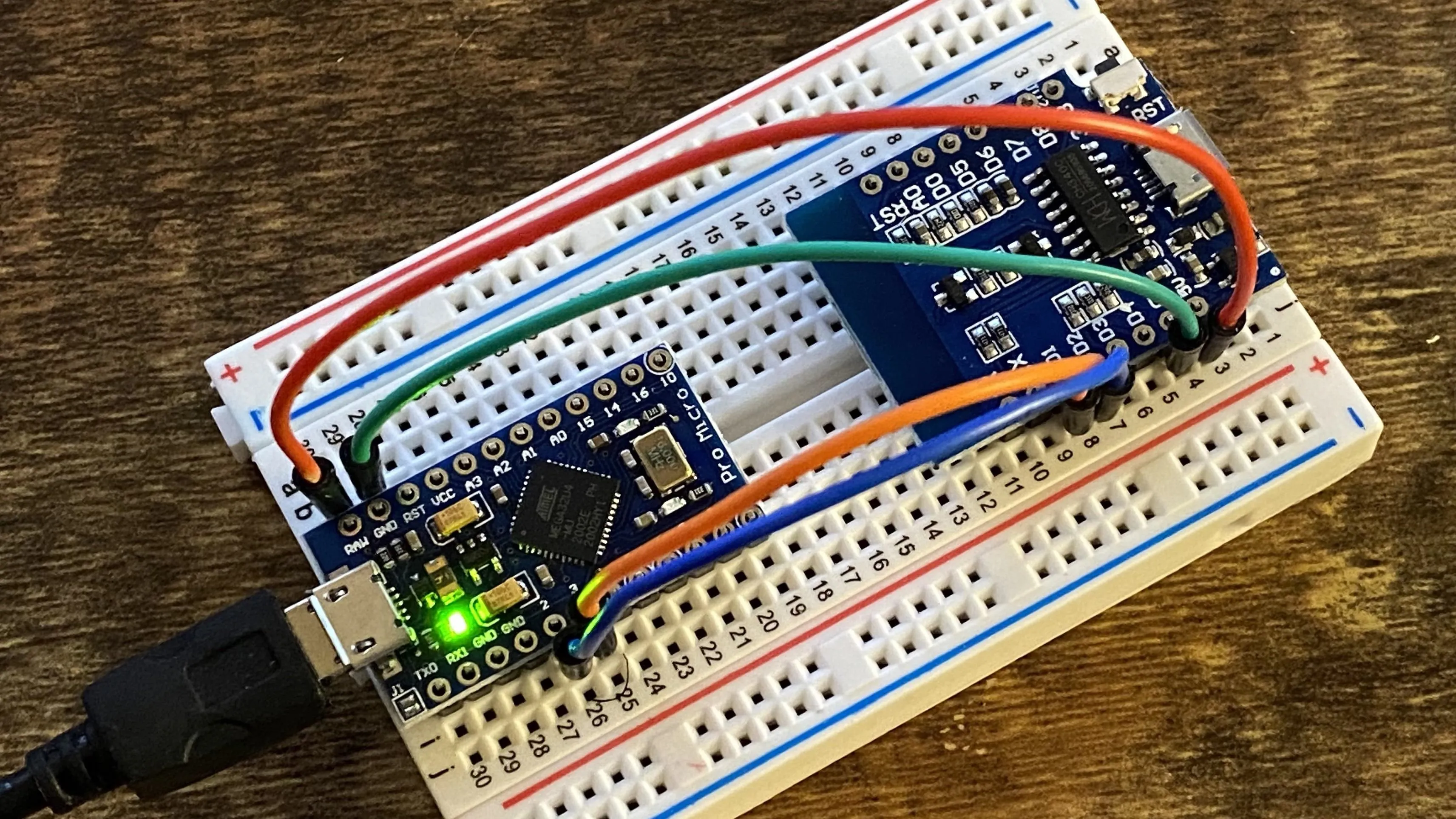
Retia/Null Byte
If your boards have DIP switches on them, make sure to check out our Cyber Weapons Lab video at around 7:14 to learn which positions the switches need to be in for programming and operating modes.
Prepare the Arduino IDE
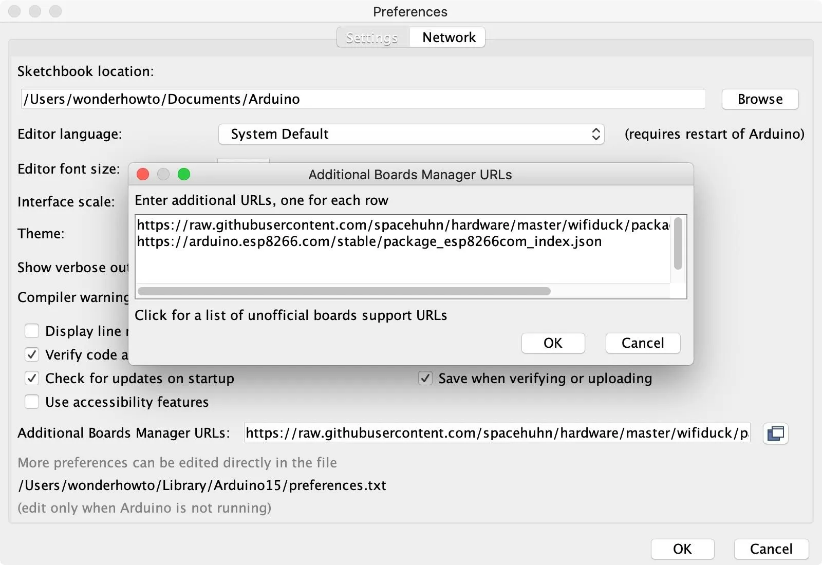
Next, we need to configure the Arduino IDE to work with both boards. Go to "Arduino" in the menu, then "Preferences." In the Additional Boards Manager URLs box, add the following two URLs, and click "OK."
- https://raw.githubusercontent.com/spacehuhn/hardware/master/wifiduck/package_wifiduck_index.json
- https://arduino.esp8266.com/stable/package_esp8266com_index.json
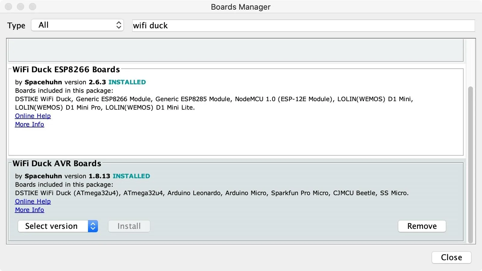
Now, go to "Tools" in the menu, hover over "Board," then select "Boards Manager." Perform a search for "wifi duck," then install both the WiFi Duck AVR Boards and WiFi Duck ESP8266 Boards options. If you already have them, make sure they're up to date. Click "Close" when done.
Download the WiFi Duck Repo
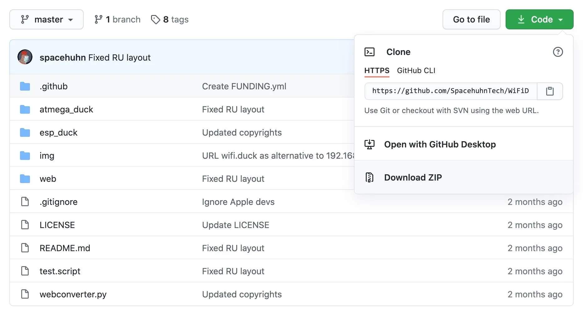
To get the code for both the ESP8266 and ATmega32U4, download the WiFi Duck repository as a zip file from GitHub. You can find it at the following link. Then unzip it on your computer.
Flash Code to the ATmega32u4
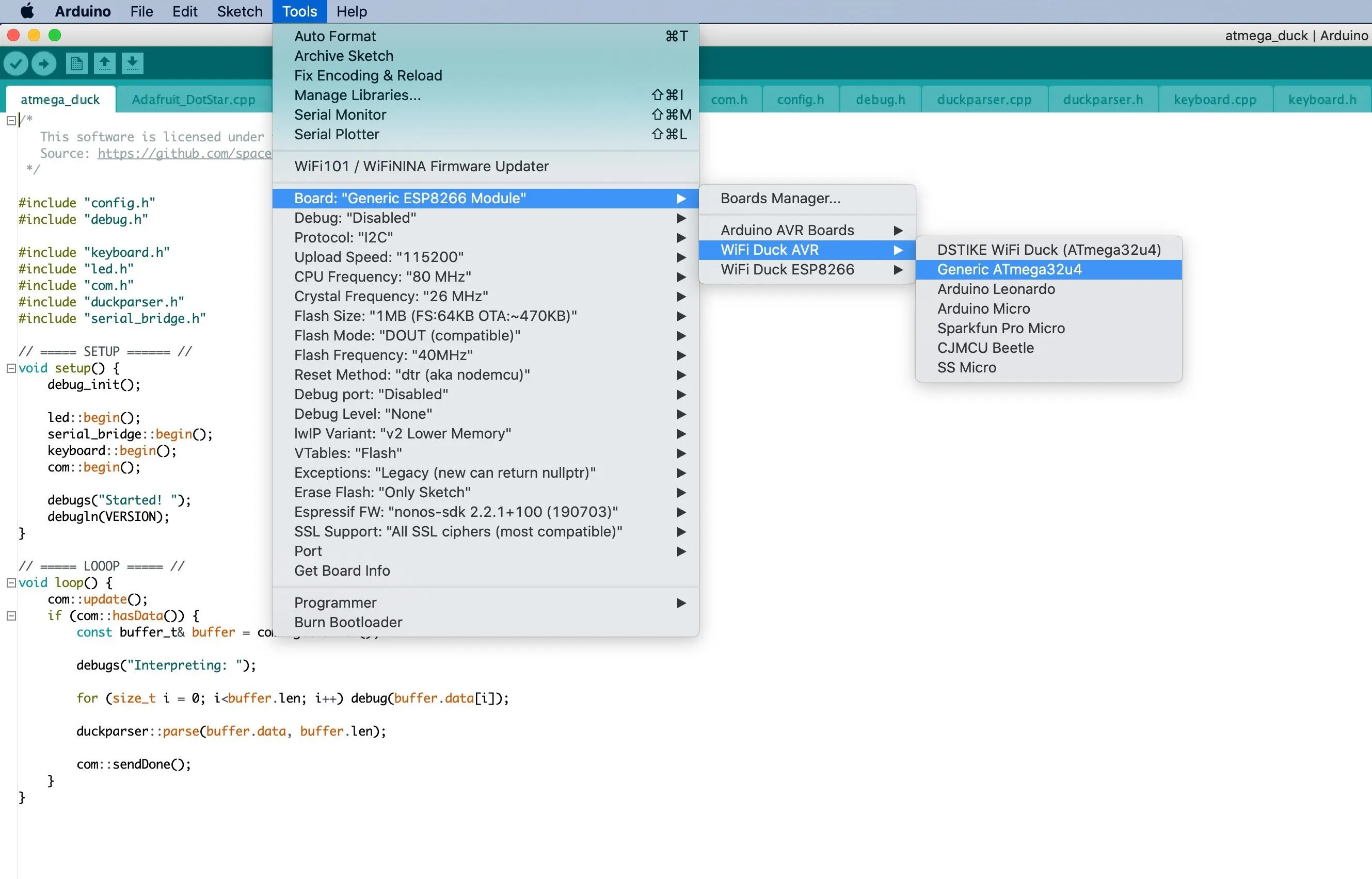
From the repo you just extracted, go into the atmega_duck folder, then open the atmega_duck.ino file in the Arduino IDE. No adjustments to the code are necessary. With it open in Arduino IDE, go to "Tools" in the menu, hover over "Board," then "WiFi Duck AVR," and choose the board that you have.
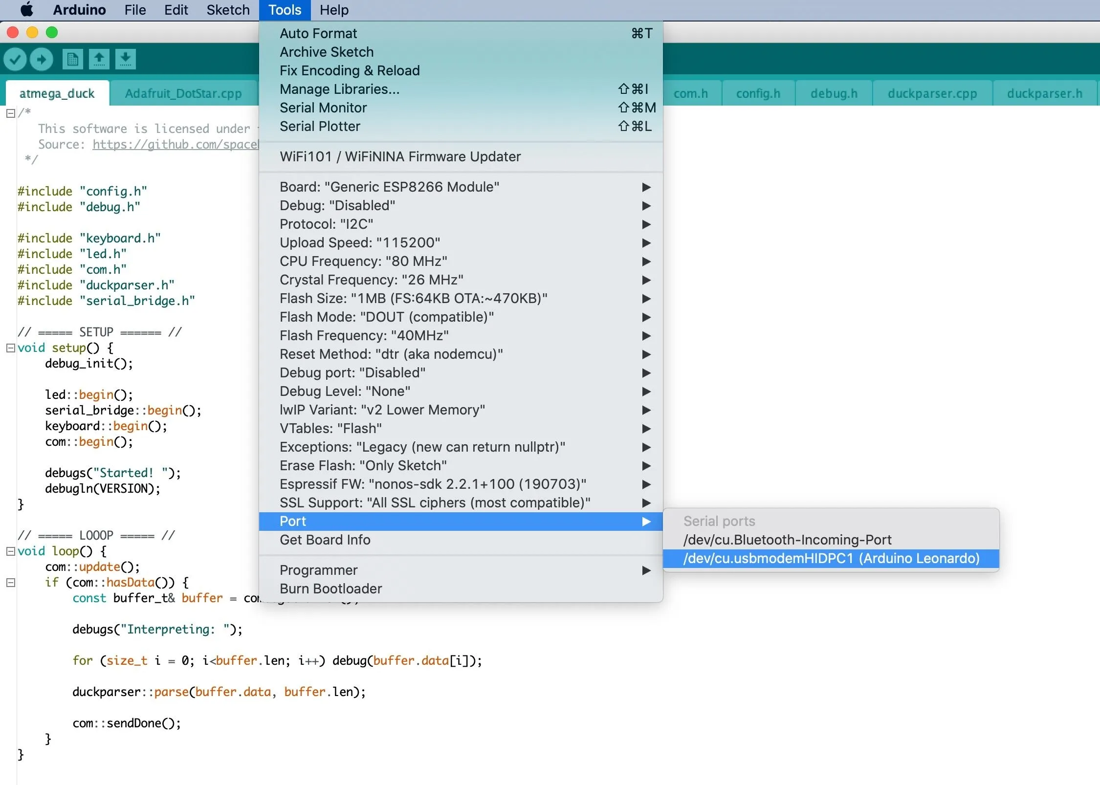
Connect the ATmega32u4 board to your computer via your Micro-USB cable, then select its port in the "Port" selection in the "Tools" menu. If you don't see your board's serial port show up, the first thing you should do is make sure you're using a proper Micro-USB cable. I had about five cables, and only one of them ended up working with data transfers.
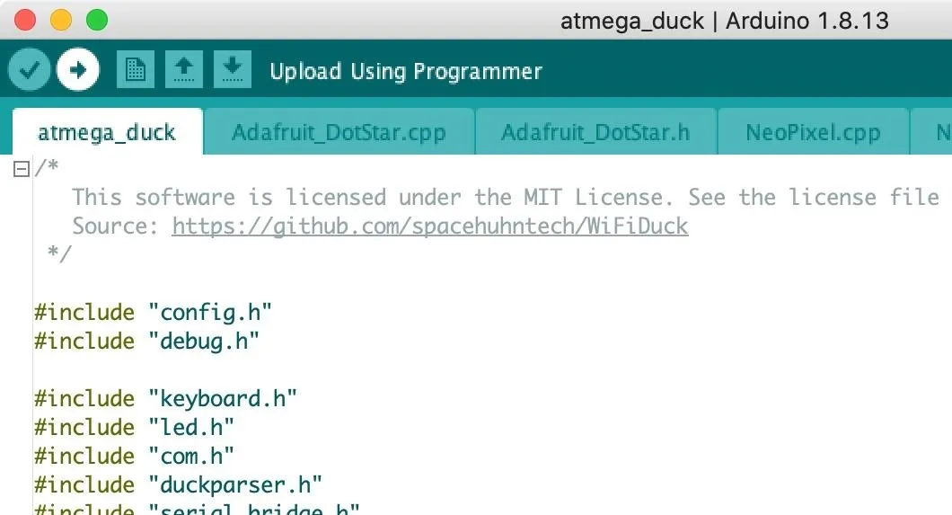
When you're done, click the "Upload" button in the project to flash the program to the board. Then just wait for the code to finish flashing over; you'll get a notification at the bottom of the project.
Flash Code to the ESP8266
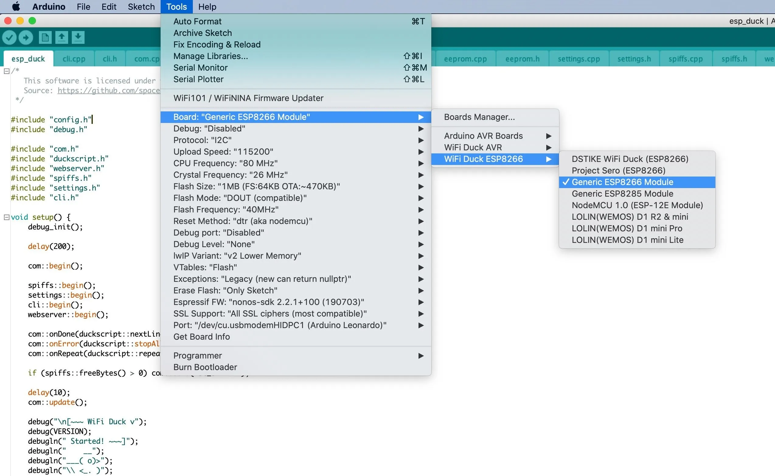
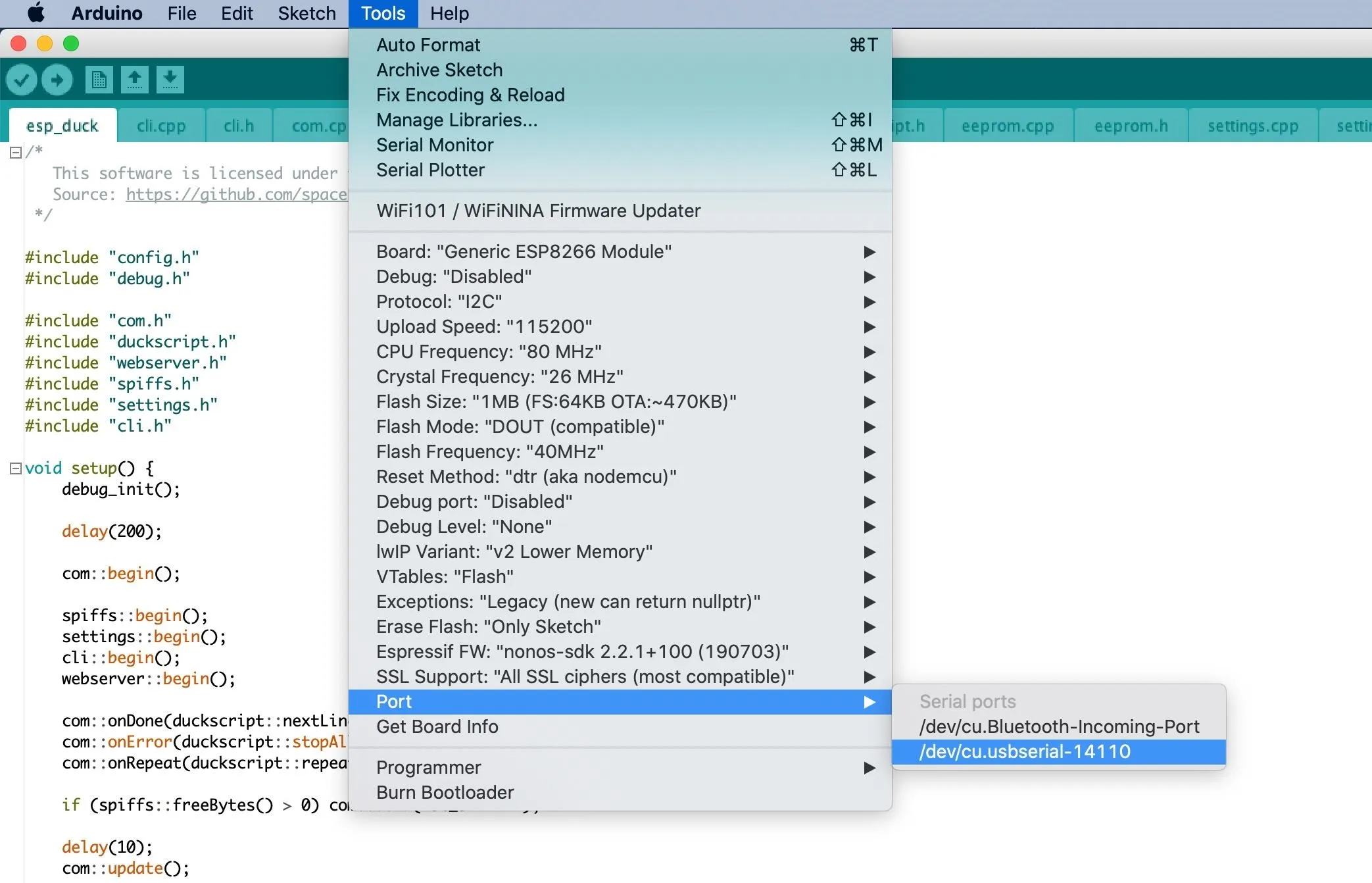
Now it's time to flash the code to your ESP8266. From the repo, go into the esp_duck folder, then open the esp_duck.ino file in the Arduino IDE. No adjustments to the code are necessary. With it open in Arduino IDE, go to "Tools" in the menu, hover over "Board," then "WiFi Duck ESP8266," and choose the board that you have.
After disconnecting the ATmega32U4, connect the ESP8266 board to your computer via your Micro-USB cable, then select its port in the "Port" selection in the "Tools" menu. Again, if you don't see your board's serial port show up, check that you're using a proper Micro-USB cable.
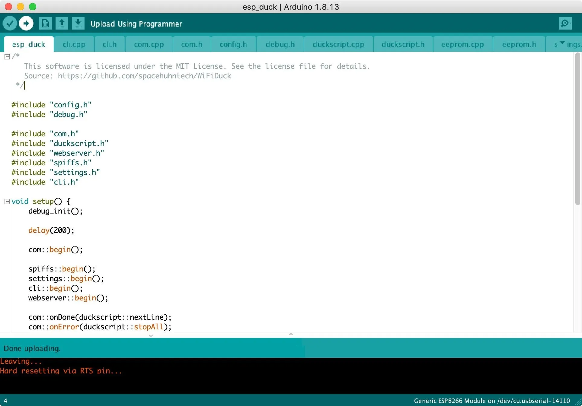
When you're done, click the "Upload" button in the project to flash the program to the board. Then just wait for the code to finish flashing over; you'll get a notification at the bottom of the project.
Connect & Run Your First Script
With everything flashed, disconnect the ESP8266 from your computer, then connect ATmega32U4 back up with the Mini-USB cable. On your computer, change your Wi-Fi connection to the network called "wifiduck" and use "wifiduck" as the password.
You won't have any internet, but you will be communicating with your WiFi Duck setup. And if your target computer is the same as your computer, you can build your payloads ahead of time and try them out on your computer to make sure they work.
Once on the right network, open a browser and visit 192.168.4.1. This interface will let you do things like run the device, save scripts, and more. To change the WiFi network's name, click on "Settings," then change the SSID and password.
Now, you can return to the main menu to write, save, and run Ducky Script payloads. There are reference scripts for you to play with and a key for all of the functions available to help write your own payloads. To do something really simple, in the Editor, try "GUI SPACE" if you're on a Mac. When you run that script, Spotlight Search should pop up.
GUI SPACETo expand that, you can add "STRING null-byte.com" to have "google.com" appear in the Spotlight Search box.
GUI SPACE
STRING null-byte.com
To open a Terminal window, change the URL to "terminal" and add "ENTER." Then, add a "DELAY 2000" so that you can write something like "STRING whoami." That will populate a Terminal window with whoami. You can add another delay and "ENTER" to actually run the command.
GUI SPACE
STRING null-byte.com
ENTER
DELAY 2000
STRING whoami
DELAY 2000
ENTER
Now, to test it out in a real-world situation, connect your computer back to your regular Wi-Fi network so you can access the internet. With the WiFi Duck still plugged into your computer, go onto another device such as your smartphone, connect to the WiFi Duck's network, visit 192.168.4.1, then run any of your scripts. And this is where I'll leave you to play around.
Cover photo and screenshots by Retia/Null Byte


Comments
Be the first, drop a comment!