


If you want to get started sniffing Wi-Fi networks, you usually need to start with a wireless network adapter. But thanks to a Wi-Fi sniffing library written in Arduino and the ultra-cheap ESP8266 chip, you might not need one. For less than $10 in electronics, you can build a tiny Arduino Wi-Fi sniffer that saves Wireshark-compatible PCAP files and fits anywhere.
Sniffing Wi-Fi packets allows you to learn a lot about the wireless landscape of an area. Even without the Wi-Fi password, you can learn about the types of devices that are nearby, which devices are connected to which networks, and more information that can be useful to a hacker. But to get started doing this, you'll typically need to invest in a wireless network adapter that gives you more control than the average consumer adapter.
While there is much debate about which wireless network adapter is the best, it can get expensive trying out which one is right for you. If some simple sniffing is all you're looking for, then it turns out a cheap, easy-to-program microcontroller might work just fine instead.
The ESP8266 for Wi-Fi Recon
The ESP8266 microcontroller can be programmed in Arduino and comes with Wi-Fi integrated, which is visible by the printed antenna on the board. These boards are also dirt-cheap, leading to many manufacturers adding them to development boards that add useful features like a USB port to connect to for easier programming of the device. While you will see many different kinds of ESP8266-based microcontrollers, they all have the same chip in the center with the distinctive antenna pattern.
One of the most popular development boards for the ESP8266 is the D1 Mini. These boards, copied widely by a number of manufacturers, are dirt-cheap and start at around three dollars. They allow for a number of pins to be used to connect to sensors or displays, and while they don't have as many pins available as a NodeMCU, the D1 Mini is also half the size.
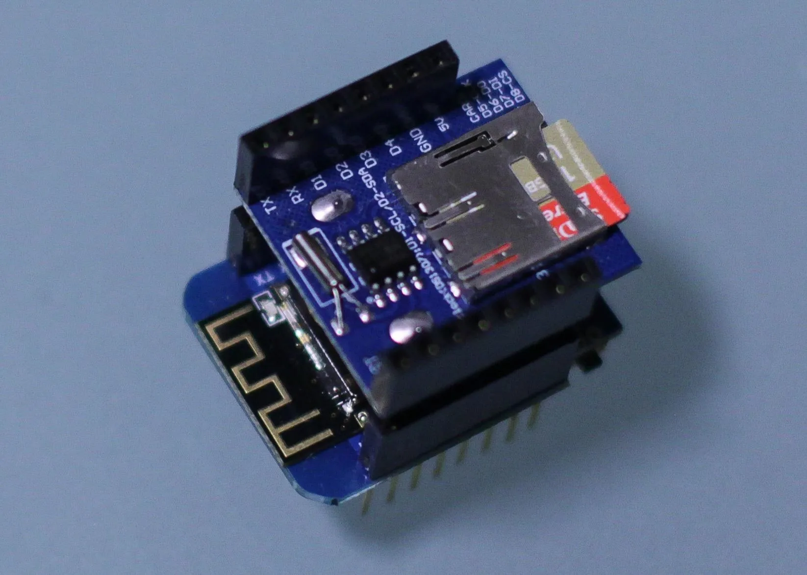
Because of the popularity among makers, there are many add-on "shields" that are sold alongside the D1 Mini, which can be stacked on top of each other to add functionality. One of the most useful D1 Mini shields is an SD card module for reading and writing data to a microSD card.
Kody/Null Byte
Spacehuhn's Arduino PCAP Library
Thanks to the efforts of Stefan Kremser, also known as Spacehuhn, an easy-to-use library for generating Wireshark-readable PCAP files can be loaded onto an ESP8266 in a matter of minutes. While the ESP8266 is a lot less powerful than most wireless network adapters, it's really cool to be able to read Wi-Fi network using nothing but a microcontroller.
There are some limitations to this, and in general, this library will work better on the more powerful ESP32, which costs a little bit more. The tradeoff is cost, and since you can get a D1 Mini plus a datalogger shield for less money (depending on where you shop), it's easy to accept the limitations of using a small, cheap microcontroller.
Once you have the library on the ESP8266 device, you'll need to get the data it's reading off of it. One of the best ways to do this is with a serial connection, which allows you to write data to your computer from the microcontroller via the serial port. While it's impressive to watch results in Wireshark come in live from a little microcontroller, we'll focus instead on a small, disconnected version that saves the traffic it logs onto a microSD card.
This form factor could be used to hide in an area where many people are to create a list of MAC addresses belonging to them, as passive Wi-Fi sniffers that could prove a device was in an area at a particular time, or as a way of understanding the network layout of an area and which devices have permission to connect to which networks. With the tiny D1 Mini, you can hide the sniffer in just about anything.
What You'll Need
First, you'll need an ESP8266-based device like the NodeMCU or the D1 Mini. I highly recommend the D1 Mini because it's exactly the right size to use with the next important piece of the puzzle, the SD card reader.
The SD card reader is important if you want to save the data to a microSD card. I recommend D1 Mini datalogger shield mentioned earlier, which you can actually get pretty cheap. This lets you just solder the pins on and stick them together to create a Wi-Fi datalogger. It includes a real-time clock, which means you'll be able to write timestamped data to any properly formatted microSD card that you have.
You'll also need a soldering iron to solder the headers that come with the D1 Mini and datalogger shield onto the D1 Mini and datalogger shield. Finally, you'll need a microSD card formatted with a Fat32 file system. Exfat will not work, I tried it.
- D1 Mini
- D1 Mini Datalogger Shield
- microSD card
- Solder and soldering iron
- Micro-USB cable
- microSD card reader
- 5 volt power supply (optional, for power away from your computer)
- CR1220 battery (optional, only for the real-time clock)
The free, cross-platform Arduino IDE will allow us to quickly prototype what we need, so make sure you have that installed on your computer. The Arduino integrated development environment allows us to quickly write and upload scripts to Arduino-like microcontroller devices.
Install the New Arduino Library
To get this project working, we'll need to install some libraries that enable everything to communicate. We need the radio of the microcontroller to save packets to the microSD card, so that means we need libraries for communicating with the microSD card and interpreting the radio signals into meaningful data to save. To install any library in Arduino is pretty simple and usually comes with some helpful example sketches to build off of.
To start, in the Arduino IDE, open the folder named "Arduino" where Arduino IDE saves your sketch files. You should see a folder called "Libraries," which should be saved in the location listed below for your OS. If you add a library here, it will then show up in the Import Library menu.
- macOS: ~/Documents/Arduino/libraries/
- Windows: My Documents\Arduino\libraries\
In a terminal window, change directory into the folder where your Arduino libraries are kept, and then use git clone to copy the Arduino PCAP repository, the Arduino Time Library, and the ESP8266 dependency from GitHub.
cd ~/Documents/Arduino/libraries/
git clone https://github.com/spacehuhn/ArduinoPcap.git
git clone https://github.com/PaulStoffregen/Time.git
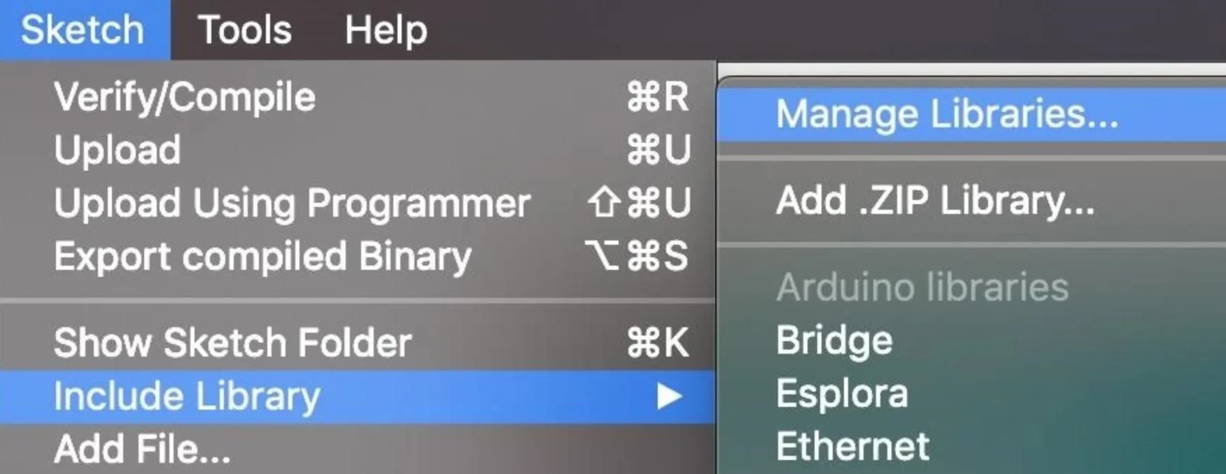
git clone https://github.com/esp8266/Arduino.gitThis is the folder that Arduino IDE checks for custom libraries every time it starts. In general, there are two ways for you to add a library. You can click on "Sketch" in the top menu bar, then "Include Library," and finally "Manage Libraries" to open the search bar.
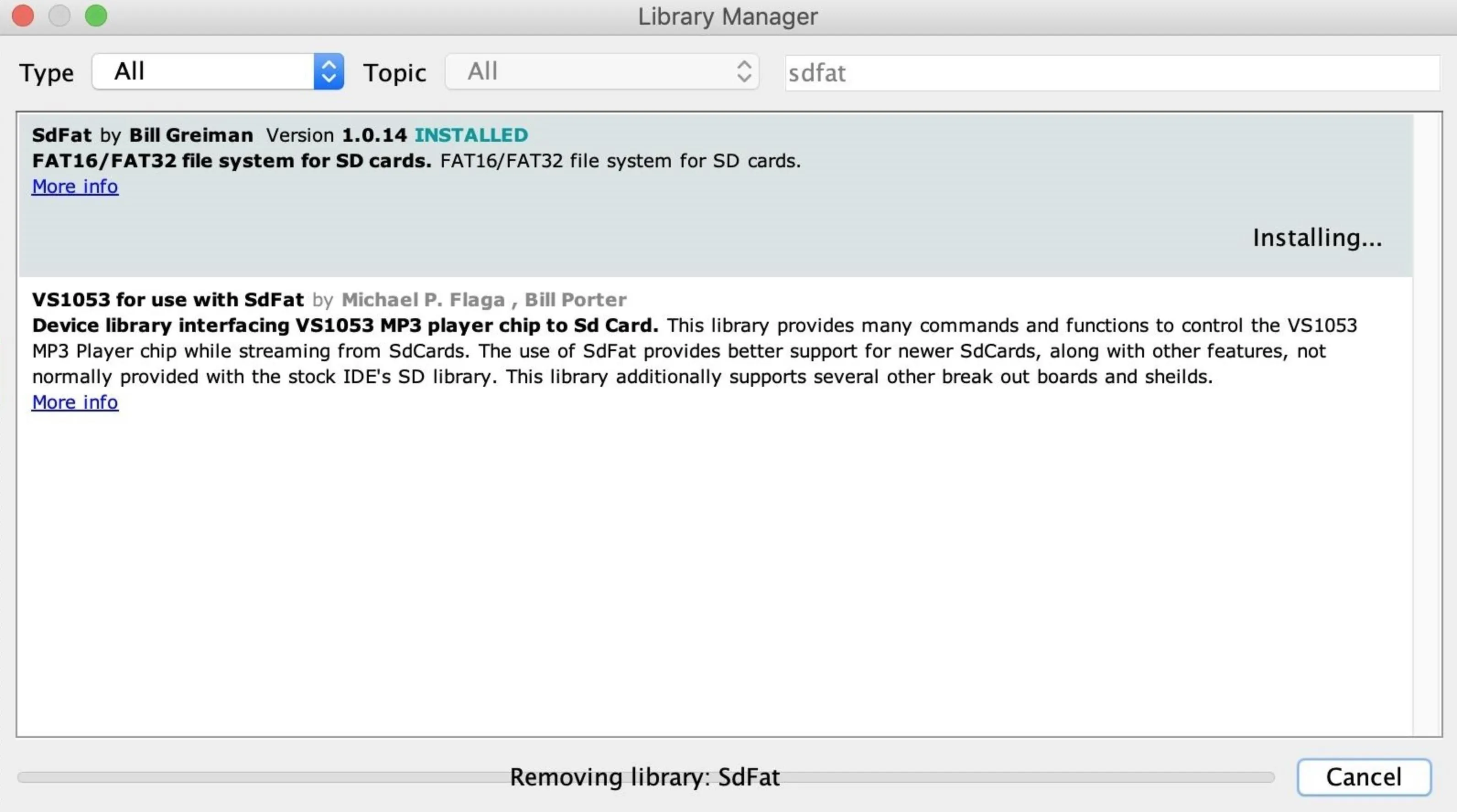
Here, you can search for libraries that are popular in the community and download them directly. This is one of the easiest ways to download things like the neopixel library from Adafruit or the SdFat library needed to write to our microSD card. Type in "sdfat," and download the SdFat library by clicking "Install." This will allow us to include it in any of our sketches from now on.
Close and restart the Arduino IDE to make sure they are all loaded.
Install the Board Library
Now, we need to tell Arduino IDE what hardware we're working with. Click on the "Arduino" drop-down menu, then select "Preferences." Next, paste the following URL into the Additional Boards Manager URLs field. Click "OK" to continue. This should add the ESP8266-related boards to the list of boards we can install.
http://arduino.esp8266.com/stable/package_esp8266com_index.jsonTo add the specific D1 Mini we're using, you'll need to click on "Tools," then hover over the "Board" section to see the list of supported boards. At the top, click "Boards Manager" to open the window that will allow us to add more boards.
When the Boards Manager window opens, type "esp8266" into the search bar. Select "esp8266" by ESP8266 Community, and install it to add support for the D1 Mini to your Arduino IDE. You may find it's already installed from the previous step, but make sure to update it if an update is available.
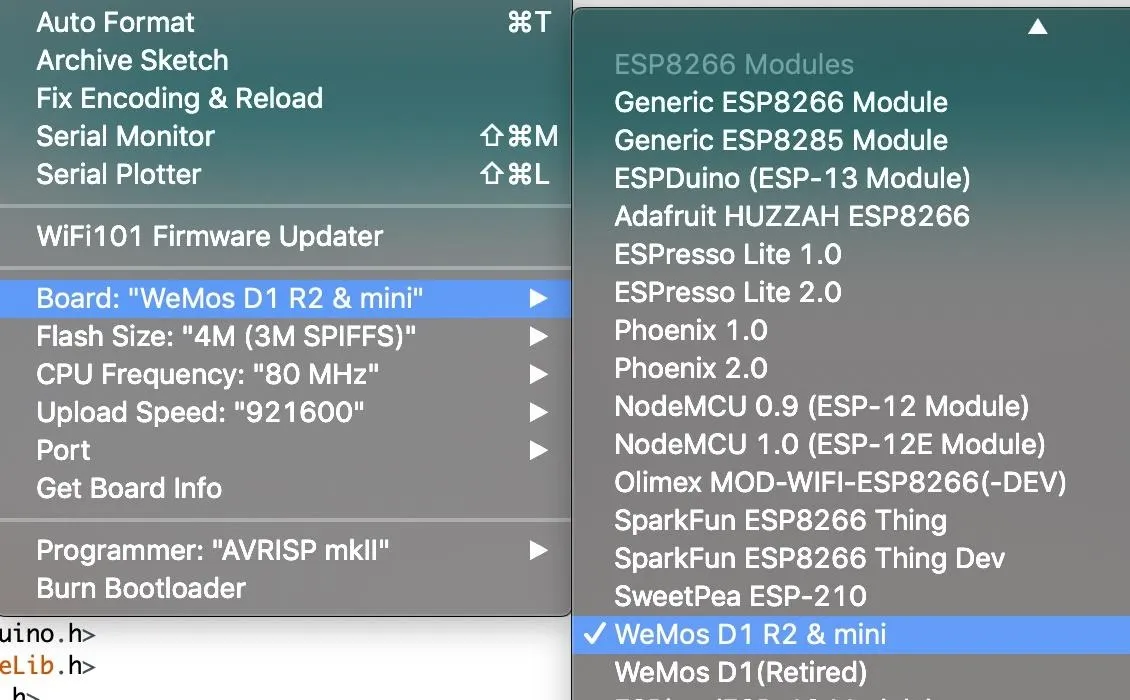
Now, you should see a section called "ESP8266 Modules" under the "Board" selector. Select the "WeMos D1 R2 & mini" board, and you should be ready to go.
Modify Any Settings in the Code
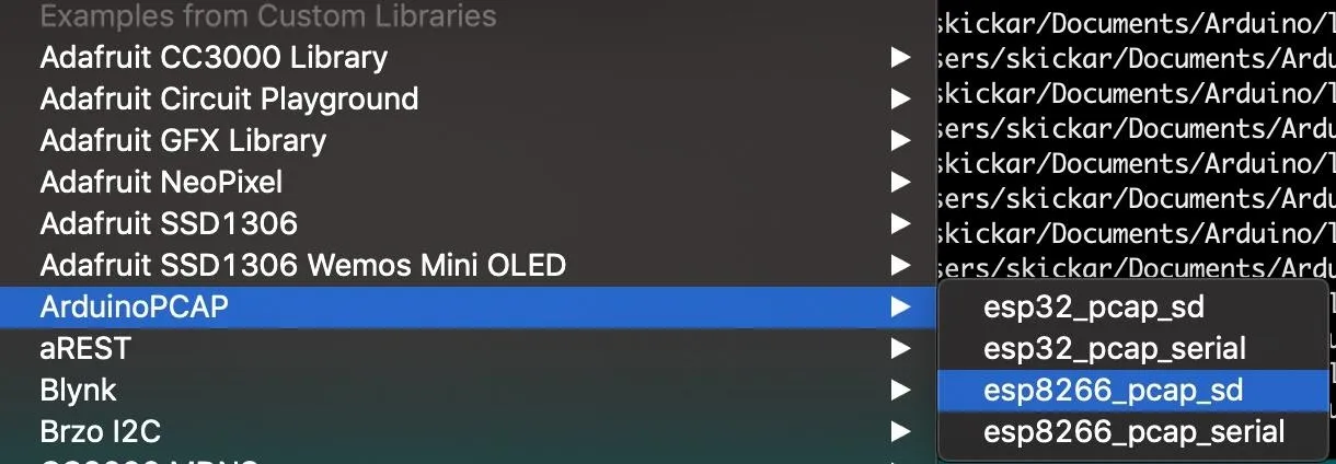
To open an example sketch to work with, go to the Arduino menu, and then click on File –> Examples –> Arduino Pcap. Here, you should see an example called "esp8266_pcap_sd" — open the sketch, as we'll be using it as a template for what we send to the D1 Mini. If you want to do this on the more powerful ESP32, you can follow the same steps and select the ESP32 instead.
Once the sketch is open, you'll see the main configuration settings.
//===== SETTINGS =====//
#define CHANNEL 1
#define FILENAME "esp8266"
#define SAVE_INTERVAL 30 //save new file every 30s
#define CHANNEL_HOPPING true //if true it will scan on all channels
#define MAX_CHANNEL 11 //(only necessary if channelHopping is true)
#define HOP_INTERVAL 214 //in ms (only necessary if channelHopping is true)
Let's start setting these so that we can sniff effectively. First, we'll set the channel for the device to sniff on. The most commonly used network channels are 1, 6 and 11, so we'll set this to 6.
#define CHANNEL 6Next, we'll decide how long we want to wait before saving the file to the microSD card. The D1 Mini doesn't have that much memory, so doing so every 30 seconds or so is a good idea. You can also name the file it generates something differently here. Increasing the time leads to larger file sizes but higher chance the device becomes overwhelmed with too much traffic.
#define FILENAME "esp8266"
#define SAVE_INTERVAL 30 //save new file every 30s
Now, let's decide if we want to channel hop or not. This will allow us to see traffic and devices using other channels, but will also chop up a lot of the packets when we switch between networks and make them unusable. As a result, this is a choice between getting a variety of packets from a lot of different channels or focusing on one channel without the worry of fragmentation. In our example, we'll avoid fragmentation by setting the value to false.
If we choose to channel hop, we can set how high the channel will go to as well. In the US, Wi-Fi networks don't use channels over 11, but other countries do. For here though, it's only useful to set it to 11.
#define CHANNEL_HOPPING false //if true it will scan on all channels
#define MAX_CHANNEL 11 //(only necessary if channelHopping is true)
If we've chosen to enable channel hopping, we can scale back some of the damage fragmentation does to our sample by setting the next value to longer. A longer value here means more time spent sniffing on each channel, leading to less packet fragmentation from samples.
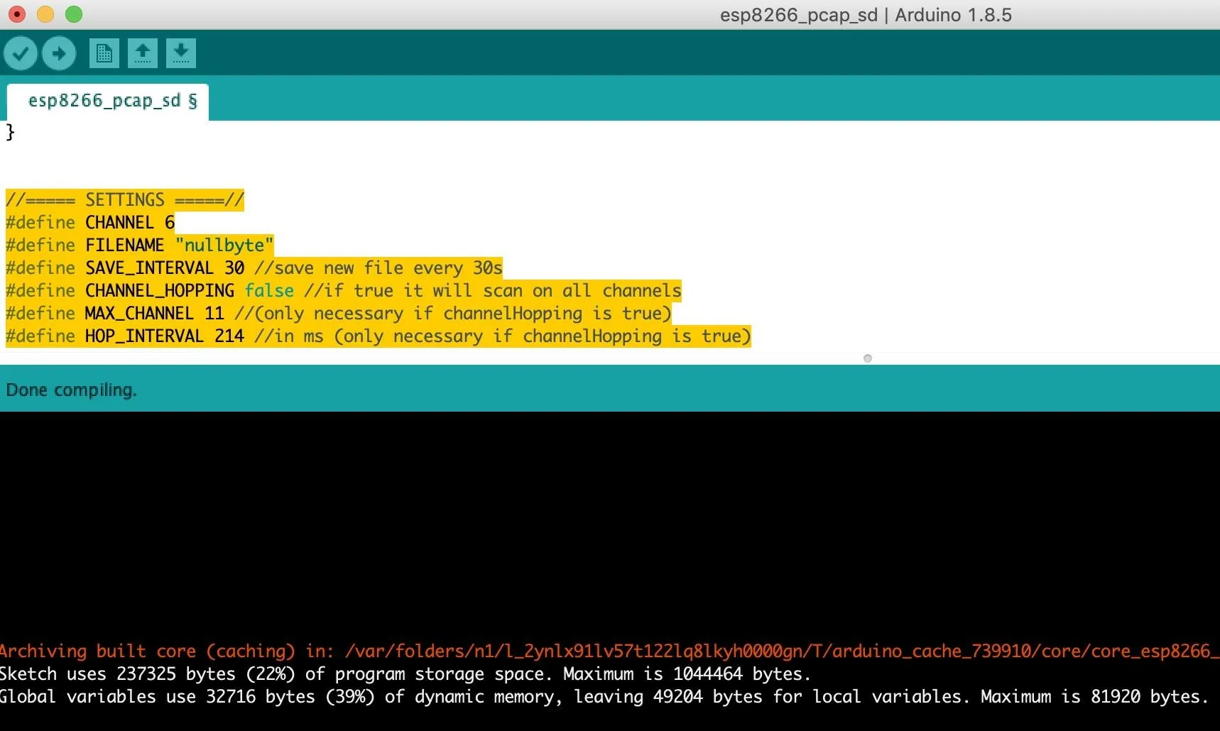
#define HOP_INTERVAL 214 //in ms (only necessary if channelHopping is true)Our control settings should now look something like this.
//===== SETTINGS =====//
#define CHANNEL 6
#define FILENAME "nullbyte"
#define SAVE_INTERVAL 30 //save new file every 30s
#define CHANNEL_HOPPING false //if true it will scan on all channels
#define MAX_CHANNEL 11 //(only necessary if channelHopping is true)
#define HOP_INTERVAL 214 //in ms (only necessary if channelHopping is true)
Connect the Hardware Together
Now, it's time to connect the hardware. If you got your D1 Mini and a data-logger shield online, you'll need to solder the pins on, which is surprisingly easy (trust me). With the D1 Mini, make sure you solder in pin headers that you can plug the data-logger down into, like in the example below.
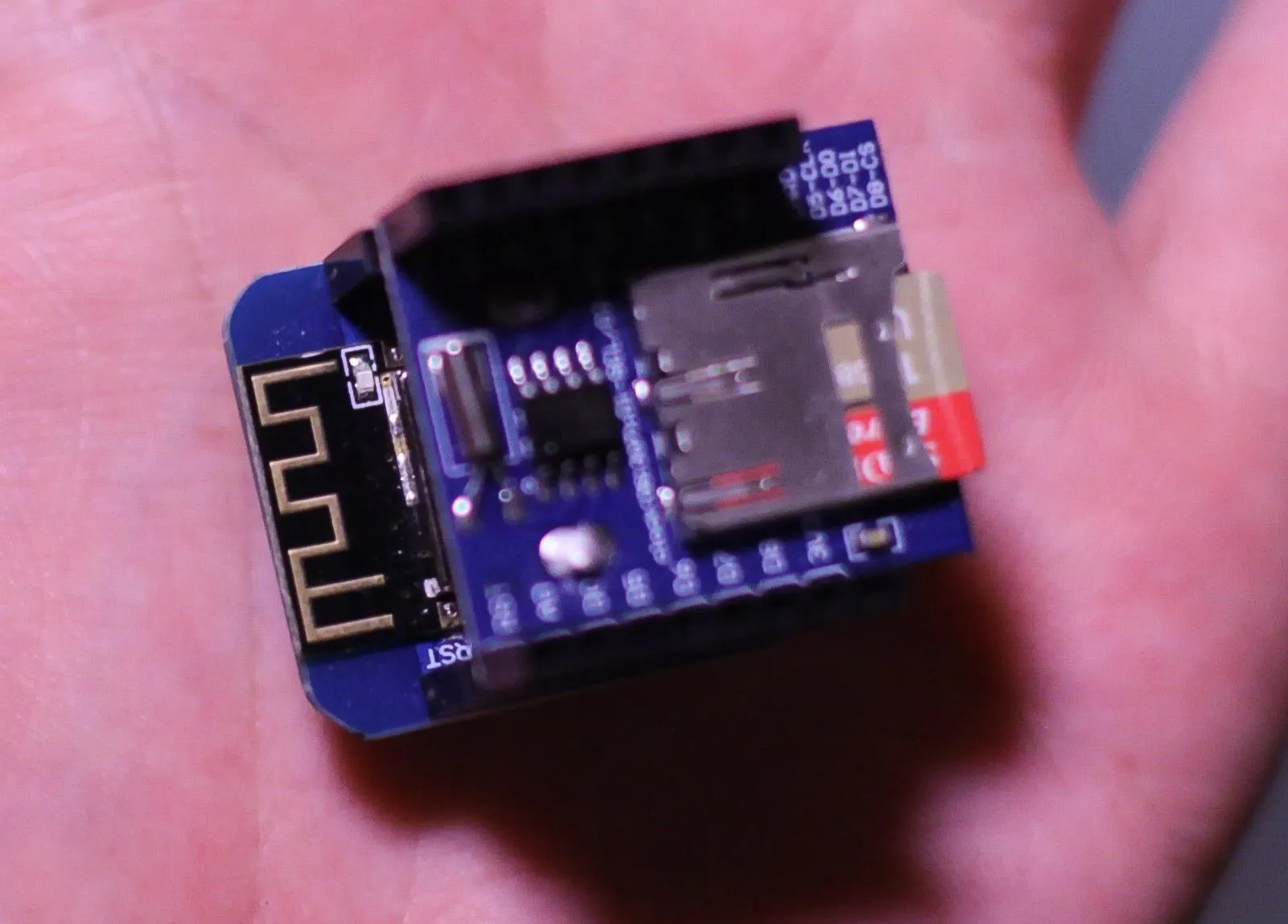
Kody/Null Byte
If you don't want to solder and want to support Spacehuhn's work, you can also buy a board from his web store.
Push the Code & Sniff Packets
Now, it's time to connect everything. Insert the microSD card into the module, plug in the USB cable to your computer and the D1 mini, and click on the "Tools" menu, then the "Port" section. You should see a "Serial" port listed, which may already be selected. If it isn't, select it here. If you don't see the right serial port, it likely means that you don't have the correct driver installed to see the D1 Mini's USB interface and will need to install it.
Once you see the serial port, you're ready to push the code! First, check that the code compiles with no errors by clicking on the check mark button on the top left of the screen. Then, click the arrow button next to the check mark to send the code to the D1 Mini.
After this is done, click on "Tools," and then "Serial Monitor" to see the status of the D1 Mini. Set the baud rate to 115,200, as it will look like random characters otherwise.
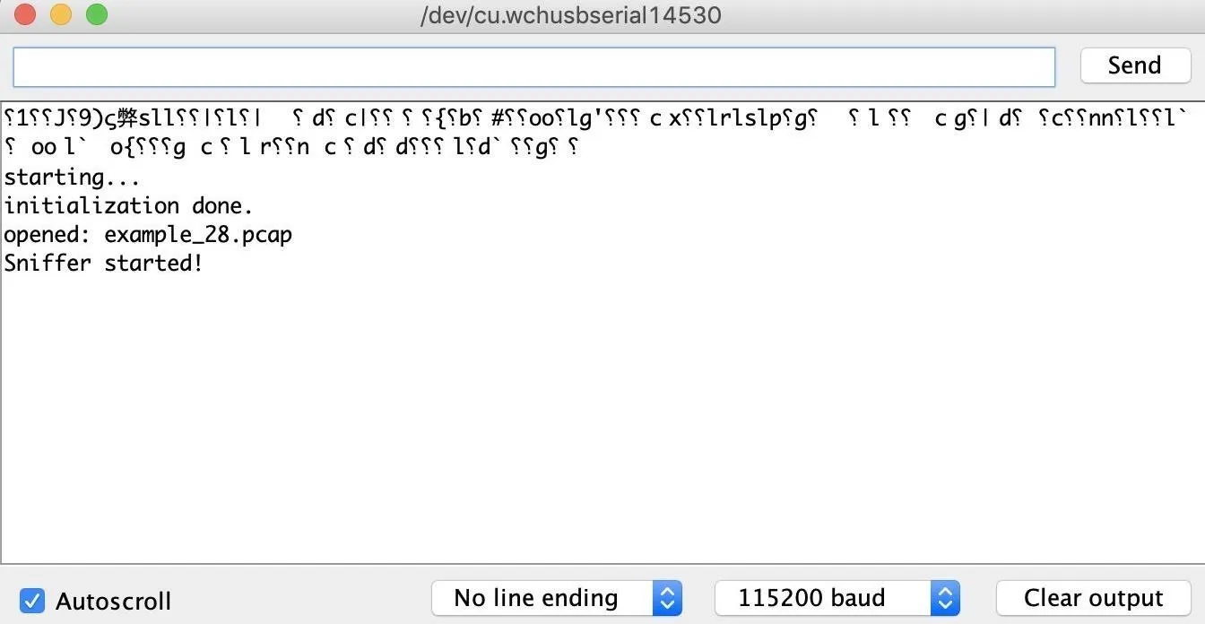
If you see a message like above, then you have success! You're able to log PCAP files to the SD card, and as soon as you're done logging, you can unplug the device, pop out the microSD, and load them it into a computer to see the results.
With a small coin cell battery to power the real-time clock and a USB power source (Micro-USB cable connected to a power adapter or computer) for the whole unit, your logger can operate independently for as long as the SD card has space.
You could also go with a battery pack via a battery shield (or another battery setup) for the D1 Mini instead of a running power via the Micro-USB port, but it's not recommended since you won't want to use the Micro-USB port at all or you'll risk frying something, plus a battery won't last long. However, one interesting idea to save power for a battery project could be to add a passive infrared sensor to only turn on the logger when movement is detected, logging Wi-Fi traffic from nearby devices any time people are detected as being present.
Tradeoffs with the ESP8266
While the Arduino PCAP library is an awesome way to get started sniffing, there are a fair amount of limitations. The ESP8266 doesn't have the range of a more powerful wireless network adapter, and it's much more likely to corrupt frames or otherwise miss recording packets for various reasons.
One thing to keep in mind is that there will always be several channels the sniffer can't listen on while it's scanning on any particular channel, so if you collect Wi-Fi traffic by scanning through every channel, you're likely to get a lot of fragmentation. Instead, setting the sniffer to listen on one channel only will make it more likely to capture everything, provided you know the channel your target network is on.
I hope you enjoyed this guide to sniffing Wi-Fi on an ESP8266 microcontroller! If you like this project and want to see more, you can support Spacehuhn on Patreon. And if you have any questions about this tutorial on the ESP8266 or if you have a comment, feel free to put it below or reach out to me on Twitter @KodyKinzie.
- Follow Null Byte on Twitter, Flipboard, and YouTube
- Sign up for Null Byte's weekly newsletter
- Follow WonderHowTo on Facebook, Twitter, Pinterest, and Flipboard
Cover photo and screenshots by Kody/Null Byte


Comments
Be the first, drop a comment!