


The most common Wi-Fi jamming attacks leverage deauthentication and disassociation packets to attack networks. This allows a low-cost ESP8266-based device programmed in Arduino to detect and classify Wi-Fi denial-of-service attacks by lighting a different color LED for each type of packet. The pattern of these colors can also allow us to fingerprint the tool being used to attack the network.
Types of Jamming Attacks
Jammers used in electronic warfare typically require equipment that overwhelms the signal of the target with radio energy, making it impossible to distinguish between the signal and the noise being introduced to the channel the target is using to communicate; This kind of jamming is popular because it works, but it also requires specialized equipment that is banned or heavily regulated in most countries.
Another type of jamming attempts to send messages that force the target to be disconnected from the network they are connected to, rather than drowning out a target's signal by trying to overwhelm it. You might think this kind of attack might only work if you are connected to the network, but this is where WPA has a severe flaw. Because so-called management frames are not encrypted, it is possible to send disruptive messages from outside the network which causes people inside the network to be unable to connect.
Deauthentication Packets
The most common way this sort of attack is done is with deauthentication packets. These are a type of "management" frame responsible for disconnecting a device from an access point. Forging these packets is the key to hacking many Wi-Fi networks, as you can forcibly disconnect any client from the network at any time. The ease of which this can be done is somewhat frightening and is often done as part of gathering a WPA handshake for cracking.
Aside from momentarily using this disconnection to harvest a handshake to crack, you can also just let those deauths keep coming, which has the effect of peppering the client with deauth packets seemingly from the network they are connected to. Because these frames aren't encrypted, many programs take advantage of management frames by forging them and sending them to either one or all devices on a network.
Dissasociation Packets
Disassociation packets are another type of management frame that is used to disconnect a node (meaning any device like a laptop or cell phone) from a nearby access point. The difference between deauthentication and disassociation frames is primarily that an AP looking to disconnect a rogue device would send a deauthentication packet to inform the device it has been disconnected from the network, whereas a disassociation packet is used to disconnect any nodes when the AP is powering down, rebooting, or leaving the area.
Common Wi-Fi Denial of Service Tools
There are many different tools to attack Wi-Fi networks, and many of them just automate more basic tools like Aireplay-ng and MDK3. We've covered both using and detecting both tools before, but in this example, we'll be setting a few design goals for detecting attacks against a network. To do that, we need to understand the way each work to effectively jam a Wi-Fi network.
Aireplay-ng is often used to disconnect clients momentarily to obtain a Wi-Fi handshake, and it uses forged deauthentication packets to disconnect any networks or clients the user specifies either with a set number of deauthentication packets, or a continuous stream. It's also used in frameworks like Airgeddon, which allow the results of scans to automatically be fed into Aireplay to actively attack any networks discovered in an area in real time.
MDK3 uses a blend of disassociation and deauthentication packets, initially having a slower onset than an Aireplay-ng attack. This attack is also used in frameworks like Airgeddon, and it can be differentiated by the alternating pattern of deauthentication and disassociation packets it sends.
Tweaking the Deauth Detector
To design a detector, I looked to find a script for the NodeMCU to base our design off of. I found Spacehuhn's DeauthDetector, which is a sketch in Arduino for ESP8266 devices like the NodeMCU that turns on an LED when a certain number of deauthentication or disassociation packets are detected. This is another of Spacehuhn's excellent designs, and you should check out his website (disable ad blockers) to see more of his ESP8266-based projects.
Inside the DeauthDetector code, I found exactly what I needed to use an LED to show the type of attack underway, rather than just turning on a light when an attack is present.
if(buf[12] == 0xA0 || buf[12] == 0xC0){This line may look similar if you followed our guide to using Wireshark to do the same thing. That's because the capture filter we used to find deauthentication and disassociation packets looks at the same elements, so we can split this code that looks for both into two different sections, one for managing a variable that tracks each kind of packet and turns on a corresponding LED to alert the user.
What You'll Need
To build this detector, you'll need a NodeMCU or ESP8266-based device. You'll also need a computer running Arduino IDE to program it, and either a three-color (RGB), four-pin LED or at least two LEDs to indicate when a packet of each type is detected. You'll need a breadboard to wire this all together as well, and it's recommended you use a resistor or potentiometer to avoid burning out your LED.
Here's a list of what I ended up using:
- ESP8266 NodeMCU CP2102 development board wireless module (less than $6 per unit)
- Solderless breadboard kit with jumper wires (around $11, but you can probably find a single breadboard with a few jumpers for less)
- Tricolor LED (around $9 for a bunch, but you can get just one at a local store for super cheap)
- Micro-USB cable (you probably already have one of these)
- Resistors (optional, if you want the LED to last longer)
Download & Configure Arduino IDE
The free, cross-platform Arduino IDE will allow us to quickly prototype what we need. Arduino IDE (the IDE stands for "integrated development environment") allows you to quickly write and upload scripts to Arduino-like microcontroller devices.
You can download the Arduino IDE from the official website. Once it's installed, you'll need to click on the "Arduino" drop-down menu, then select "Preferences." Next, paste the following URL into the Additional Boards Manager URLs field. Click "OK" to continue.
http://arduino.esp8266.com/stable/package_esp8266com_index.json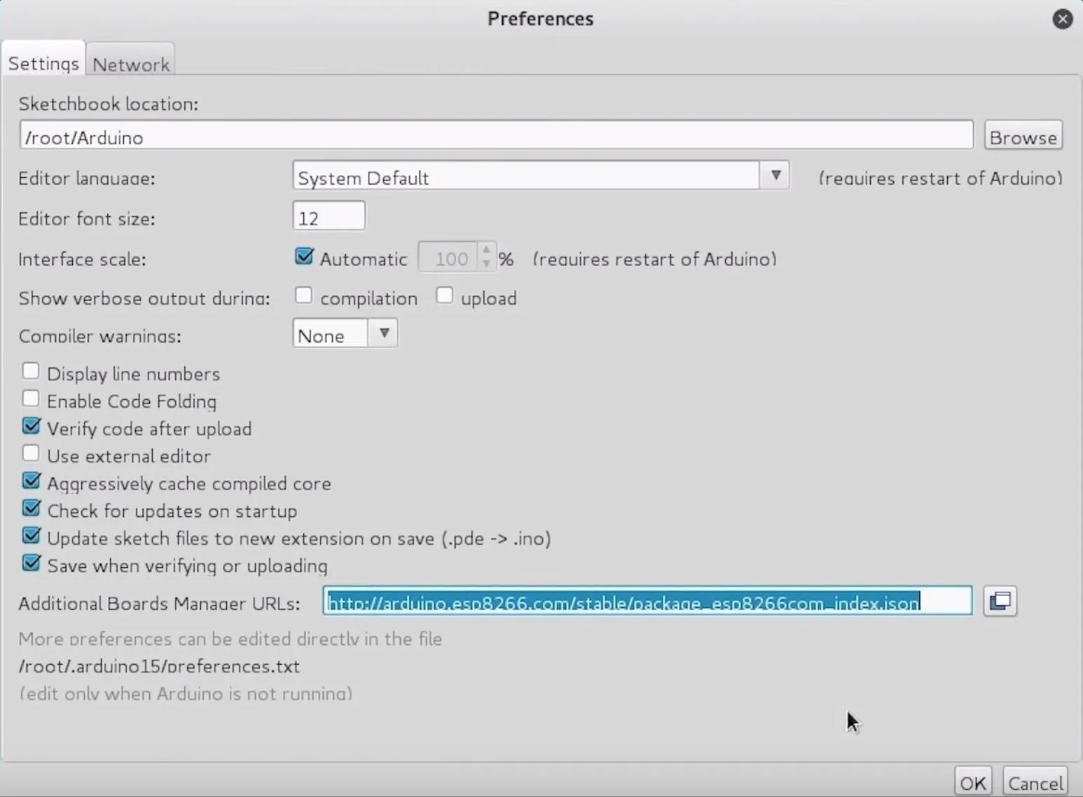
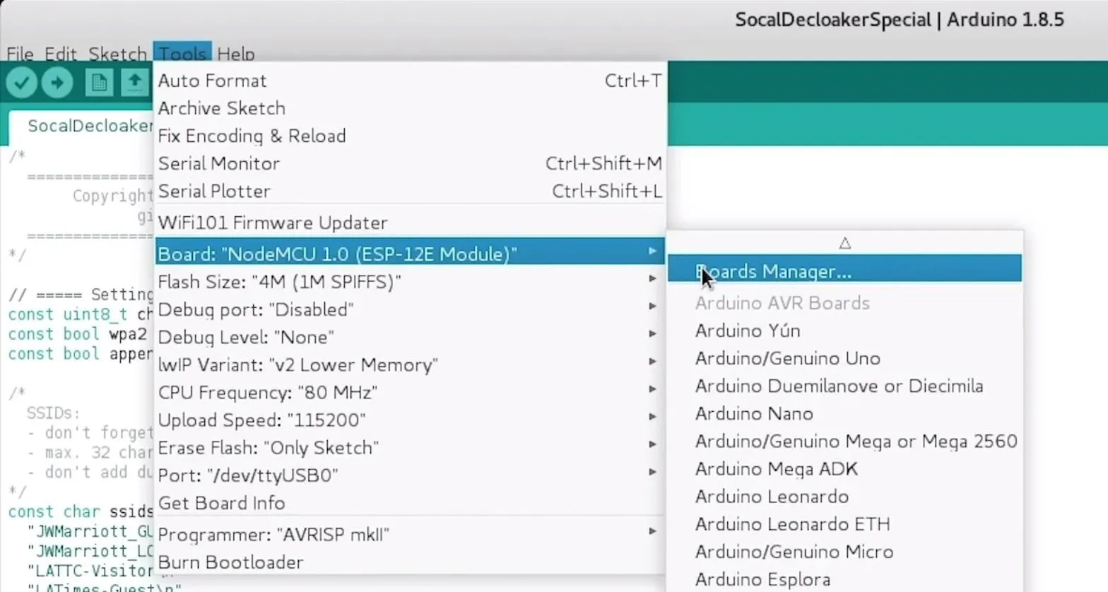
Next, you'll need to add the NodeMCU to the Boards Manager. To do this, you'll need to click on "Tools," then hover over the "Board" section to see the drop-down list of supported boards. At the top, click "Boards Manager" to open the window that will allow us to add more boards.
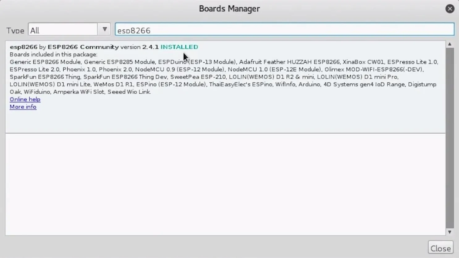
When the Boards Manager window opens, type "esp8266" into the search bar. Select "esp8266" by "ESP8266 Community," and install it to add support for the NodeMCU to your Arduino IDE.
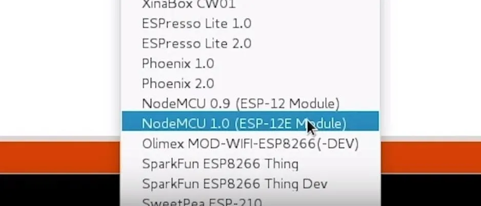
Once this is done, you should be ready to program your NodeMCU. Plug your NodeMCU into your breadboard and your NodeMCU into the computer. When you click on "Tools," you should see the correct port auto-selected. Select the "NodeMCU 1.0."
If you're using a bad cable, the port may not show up, so if you don't see anything after you've completed the other steps, try another cable first.
Download the DeauthDetector
Now that we have our IDE set up, we can download Spacehuhn's DeauthDetector to get started modifying the code. You can download the original version here if you'd like to follow along, but I'll be using my forked version below for our example.
In a terminal window, type the following to download the modified DeauthDetector, change to its directory, and list the contents.
git clone https://github.com/skickar/DeauthDetector.git
cd DeauthDetector
ls
Once inside the new folder containing the downloaded files, you'll see an INO sketch file and two libraries that we will need for the project to work. Open the INO file in Arduino IDE, then click on "Sketch" in the menu at the top. Select "Add File" to select the two libraries we downloaded along with the INO file. Make sure to add mac.cpp and mac.h or our code will fail.
Once we have the library added, we can push the code to our NodeMCU, but let's take a look inside the code and see how it works.
Tweak the Deauth Detector Code
First and most obviously, we have our main settings. There are a collection of definitions that dictate how the code functions. Here, we can define whether or not we want to channel hop or just stay on one channel by setting the "channelHopping" setting to "true."
Depending on where we are, we can define the highest channel to scan to while channel hopping (Japan is 14, while the US only goes to 11), and the number of packets detected per minute which we will decide an attack is underway. Because we are tweaking the detector, this won't be so important.
//===== SETTINGS =====//
#define channel 1 //the channel it should scan on (1-14)
#define channelHopping true //scan on all channels
#define maxChannel 13 //US = 11, EU = 13, Japan = 14
#define ledPin 2 //led pin ( 2 = built-in LED)
#define inverted false // invert HIGH/LOW for the LED
#define packetRate 3 //min. packets before it gets recognized as an attack
Next, we have a series of variables which keep track of things in the script. I've added two variables to keep track of deauthentication and disassociation packets, creatively named "dissoc" and "deauth."
#define scanTime 500 //scan time per channel in ms

//Mac from;
//Mac to;
unsigned long c = 0;
unsigned long deauth = 0;
unsigned long dissoc = 0;
unsigned long prevTime = 0;
unsigned long curTime = 0;
int curChannel = channel;
Next, we have a sniffer function, and an "if" statement that adds to the "c" counter, which is counting how many deauthentication or disassociation packets we have received. I've commented this out because we will be tracking them individually.
void sniffer(uint8_t *buf, uint16_t len) {

/*    if(buf[12] == 0xA0 || buf[12] == 0xC0){

      c++;
    }
*/
Instead, we'll insert two "if" statements that will add to a cooldown timer. Whenever we detect disassociation packets, we'll turn on an LED by setting the cooldown timer to 500, and then subtract one from the timer one each time we scan a packet that isn't a dissociation packet. This means the light will stay on continuously when an attack is underway and turn off as soon as the attack stops and normal traffic resumes. The same logic is true for deauthentication packets, which we track in the second "if" statement.
if(buf[12] == 0xA0){
      dissoc = 500;
    }
        if(buf[12] == 0xC0){
      deauth = 500;
    }
Now, we'll decide what happens when the packet doesn't match, meaning it's a normal Wi-Fi packet and not one we're looking for. To handle this, we'll use an "else" clause that says that if the cooldown timer for "deauth" or "dissoc" is equal to or greater than one, subtract one from the timer. Otherwise, if the timer is already at zero, do nothing.
else{
      if (deauth >= 1){
      deauth--;}
      if (dissoc >= 1){
      dissoc--;}
    }
In our setup loop, we'll set up our pins for output mode and Spacehuhn's sniffer functions get to work scanning for packets. We specify we want to turn on pins D5, D6, and D7 with the pinMode(pin, mode) function, in this case turning the pins on for output mode. This code will let us control the LEDs from these pins.
void setup() {
  Serial.begin(115200);

  wifi_set_opmode(STATION_MODE);
  wifi_promiscuous_enable(0);
  WiFi.disconnect();
  wifi_set_promiscuous_rx_cb(sniffer);
  wifi_set_channel(curChannel);
  wifi_promiscuous_enable(1);

  pinMode(D5, OUTPUT);
  pinMode(D6, OUTPUT);
  pinMode(D7, OUTPUT);
  }
Now, we have our main loop, the part of the code that runs over and over again. In this section of the code, we define the time and define the logic that actually turns on the LEDs.
void loop() {
  curTime = millis();

  if(curTime - prevTime >= scanTime){
    prevTime = curTime;
In this section, we set up what happens depending on the value of our cooldown timer, which starts at zero but gets set to 500 each time there is a deauthentication or disassociation packet. Each is tracked separately and one is subtracted from each every time a normal packet is detected if the cooldown timer isn't already zero. Here, we simply say that if the cooldown timer is one or more, turn on the LED by turning the corresponding pin high. Also included is the logic for inverting the LED, which you can set true or false at the beginning.
if(deauth >= 1){
      if(inverted) digitalWrite(D5, LOW);
      else digitalWrite(D5, HIGH);}
      else{
      if(inverted) digitalWrite(D5, HIGH);
      else digitalWrite(D5, LOW);
    }
    if(dissoc >= 1){
      if(inverted) digitalWrite(D7, LOW);
      else digitalWrite(D7, HIGH);
      }
      else{
      if(inverted) digitalWrite(D7, HIGH);
      else digitalWrite(D7, LOW);
    }
Finally, we say that if the value of the cooldown timer is "else" (in this case, less than one), to turn off the LED. This is the last of our modifications, and the last part of the code controls the channel hopping and sets the NodeMCU to scan on the next channel, assuming channel hopping is enabled.
if(channelHopping){
      curChannel++;
      if(curChannel > maxChannel) curChannel = 1;
      wifi_set_channel(curChannel);
    }
  }

}
The final code should look like this:
#include <ESP8266WiFi.h>
#include "Mac.h"
extern "C" {
#include "user_interface.h"
}
//===== SETTINGS =====//
#define channel 1 //the channel it should scan on (1-14)
#define channelHopping true //scan on all channels
#define maxChannel 13 //US = 11, EU = 13, Japan = 14
#define ledPin 2 //led pin ( 2 = built-in LED)
#define inverted false // invert HIGH/LOW for the LED
#define packetRate 3 //min. packets before it gets recognized as an attack
#define scanTime 500 //scan time per channel in ms
unsigned long deauth = 0;
unsigned long dissoc = 0;
unsigned long prevTime = 0;
unsigned long curTime = 0;
int curChannel = channel;
void sniffer(uint8_t *buf, uint16_t len) {
if(buf[12] == 0xA0){
dissoc = 500;
}
if(buf[12] == 0xC0){
deauth = 500;
}
else{
if (deauth >= 1){
deauth--;}
if (dissoc >= 1){
dissoc--;}
}
//}
}
void setup() {
Serial.begin(115200);
wifi_set_opmode(STATION_MODE);
wifi_promiscuous_enable(0);
WiFi.disconnect();
wifi_set_promiscuous_rx_cb(sniffer);
wifi_set_channel(curChannel);
wifi_promiscuous_enable(1);
pinMode(D5, OUTPUT);
pinMode(D6, OUTPUT);
pinMode(D7, OUTPUT);
Serial.println("starting!");
}
void loop() {
curTime = millis();
if(curTime - prevTime >= scanTime){
prevTime = curTime;
Serial.println((String)c);
if(deauth >= 1){
if(inverted) digitalWrite(D5, LOW);
else digitalWrite(D5, HIGH);}
else{
if(inverted) digitalWrite(D5, HIGH);
else digitalWrite(D5, LOW);
}
if(dissoc >= 1){
if(inverted) digitalWrite(D7, LOW);
else digitalWrite(D7, HIGH);
}
else{
if(inverted) digitalWrite(D7, HIGH);
else digitalWrite(D7, LOW);
}
if(channelHopping){
curChannel++;
if(curChannel > maxChannel) curChannel = 1;
wifi_set_channel(curChannel);
}
}
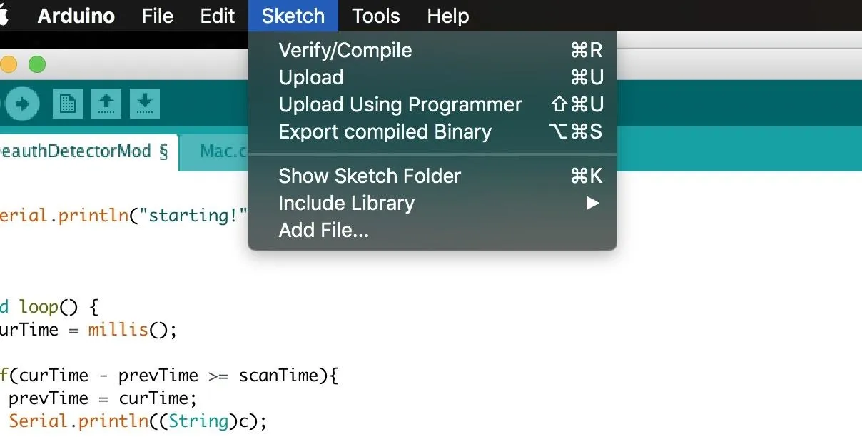
}When the modifications are complete (or when you're ready since it's already done in our example), you can press the arrow icon in the top left of Arduino IDE to push your code to the NodeMCU.
Wire & Test the Modified DeauthDetector
Once you have the code pushed to the NodeMCU, you can wire your four-pin, three-color RGB LED in one of two ways. Most direct is plugging it directly next to the D5, D6, D7, and ground pins on the mini breadboard. This works great, and probably won't burn out the LED, but to be safe, you may want to use a resistor in your design.
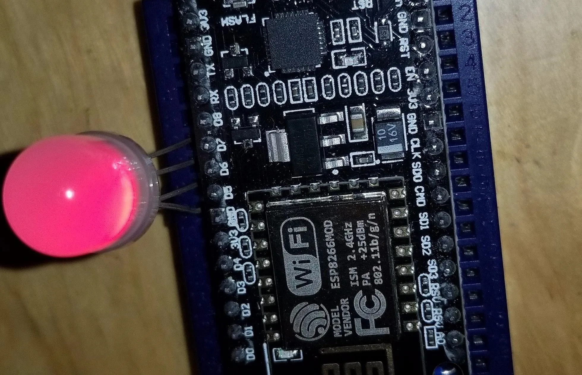
To include a resistor, place it between the ground pin and whichever ground pin you are using on the NodeMCU.
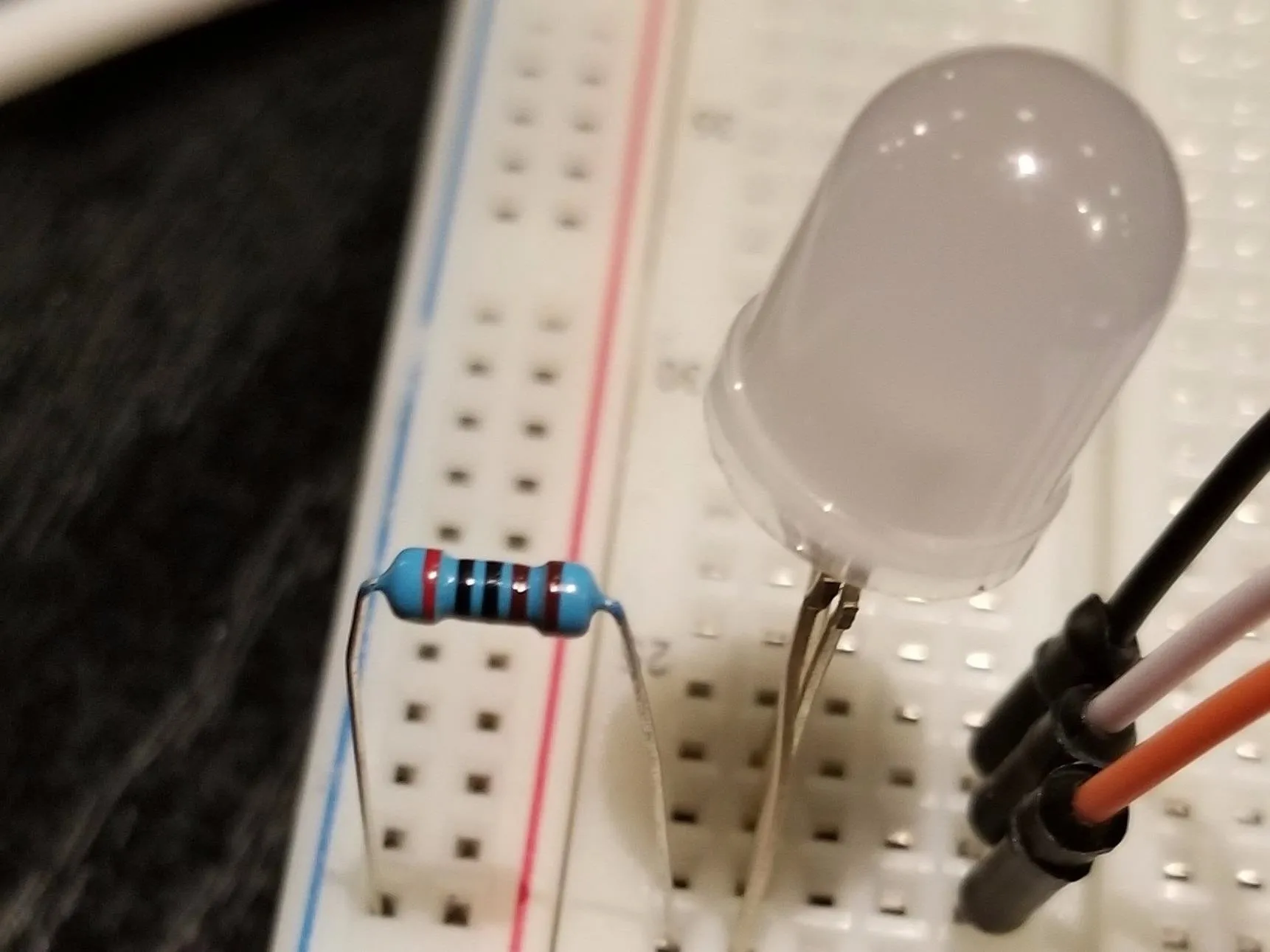
Once this is wired, you should be ready to go!
Follow our guides to using MDK3 and Airplay-ng to fire off some hostile packets against a network you have permission to, and see if the LED lights up in response. In addition, watch for patterns in the colors that appear, as they'll directly reflect the behavior of the program being used.
You can check our guide on launching Wi-Fi denial of service attacks below. Be warned, these attacks are very illegal against networks you don't have permission to test, so make sure you have permission before doing so.
- More Info: Use MDK3 for Advanced Wi-Fi Jamming
Handheld Wi-Fi Jamming Detector
This tool is a great way of visualizing Wi-Fi attacks and allows anyone to see when an attack is present and what kind of Wi-Fi packets are involved with a minimum of work. Rather than needing Wireshark running to see what's going on around you, this simple project shows whether an attack is in progress and, if so, what kind of attack is being used.
I hope you enjoyed this guide to detecting and classifying Wi-Fi jamming attacks with the NodeMCU. If you have any questions about this tutorial on detecting Wi-Fi attacks or you have a comment, feel free to reach me on Twitter @KodyKinzie.
- Follow Null Byte on Twitter, Flipboard, and YouTube
- Sign up for Null Byte's weekly newsletter
- Follow WonderHowTo on Facebook, Twitter, Pinterest, and Flipboard
Cover photo and screenshots by Kody/Null Byte


Comments
Be the first, drop a comment!