


For anyone interested in using cheap, Wi-Fi-connected microcontrollers like the ESP8266, the Arduino programming language can be a barrier to entry. Based on C++, Arduino requires knowledge of more computer science than languages like Python. Fortunately for beginners, setting up MicroPython on an ESP8266 allows anyone to write Python on affordable microcontrollers in a matter of minutes.
Cheap Prices Come with a Learning Curve
One of the first languages many people learn for programming electronics is Arduino, which requires knowledge of the specific structure needed to make a sketch work. Because of the way microcontrollers run code, even a simple Arduino sketch will typically consist of two functions: setup and loop.
To write a sketch that blinks an LED attached to pin D1 (also called GPIO pin 5), we can use the following sketch in Arduino to set the LED to output, turn it on for a second, and then turn it off for a second.
void setup() {
  pinMode(D4, OUTPUT);
}
void loop() {
  digitalWrite(D4, HIGH);   // turn the LED on (HIGH is the voltage level)
  delay(1000);                       // wait for one second
  digitalWrite(D4, LOW);    // turn the LED off by making the voltage LOW
  delay(1000);                       // wait for another second
}
For this seemingly simple action, we have a lot of code that seems pretty unintuitive for a beginner to understand. What's happening in this program is that the setup function runs once, turning our D4 pin to output mode, and then the loop runs continuously to turn on and off the LED. While this is a simple sketch, MicroPython can make it even easier.
MicroPython to the Rescue
In MicroPython, we can do the same in a way that's clearly understandable in two lines. First, we import the modules we need, and then we spell out what we want to do in clear and straightforward Python.
from time import sleep; from machine import Pin; led = Pin(2, Pin.OUT) # Imports modules and defines output pin 5
while True: led.on(); sleep(1); led.off(); sleep(1) # Blinks LED on and off forever
If we want to get more technical, we can even write a function to read whether the LED is on or off and switch its state every second, all on the same line. This would require more setup on Arduino and is an excellent example of how MicroPython can make simple coding easy.
We can also use Python tricks like ternary operators to make our code more compact without being too difficult to understand. In this structure, conditions are written as
from time import sleep; from machine import Pin; led = Pin(2, Pin.OUT);
while True: led.value(1) if (led.value() == 0) else led.value(0); sleep(1)
Reading MicroPython vs. Arduino
Of course, programming isn't about making your code as short as possible. If you want to abuse both languages, it's possible to write our code to blink an LED on a single line, but it's difficult to understand and generally not good practice. Here, we can see an abused one-line MicroPython program.
exec("import time; machine; led = Pin(2, Pin.OUT)\nwhile True: led.on(); sleep(1); led.off(); sleep(1)")While this is definitely more difficult to read than the two-line version above, it's still much easier to understand than the abused Arduino version below.
void setup() {pinMode(D4, OUTPUT);}void loop(){digitalWrite(D4,1);delay(1000);digitalWrite(D4,0);delay(1000);}MicroPython's real value isn't being more compact than Arduino. In general, those new to microcontrollers will have an easier time understanding and writing MicroPython code, as led.on() is a much easier command to remember than digitalWrite(D1,0) for turning on an LED.
REPL & Web REPL
Another feature of MicroPython is the ability to run code line by line, rather than needing to first compile it like in Arduino. That means if you want to start writing a program or working with a piece of hardware, you can connect to the REPL (read, evaluate, print loop) via a serial connection and input commands directly — no need to write an entire sketch first.
There are many advantages to this, and while the REPL command-line interface isn't the only way to work with MicroPython, it's by far the fastest and easiest way to get started writing code on your microcontroller. Of course, we can also write Python files and upload them as well, but the simple ability to connect to an ESP8266 and create a Wi-Fi network in real-time is pretty amazing.
MicroPython v1.11-8-g48dcbbe60 on 2019-05-29; ESP module with ESP8266
Type "help()" for more information.
>>> print("Hello world!")
Hello world!
>>>
This simple interface is available from the command line any time you connect your ESP8266 via a USB cable, and it can even be configured to work over Wi-Fi as well.
What You'll Need
To use MicroPython, you'll need an ESP8266-based microcontroller, such as the D1 Mini or NodeMCU. These boards are cheap and easy to find on websites like AliExpress and Amazon.
You'll also need a computer with Python3 installed and a Micro-USB cable to connect to the board. You'll need an internet connection to download the MicroPython firmware binary, a breadboard for connecting components, and a three-color RGB LED to test our output pins. If you don't have a three-color RGB LED, you can use regular LEDs as well.
Kody/Null Byte
Download the ESPtool
To download the tool we'll need for flashing to our ESP8266, we need to use Python's package manager, Pip. To do so, we can run the following command. If this doesn't work, you can also try replacing pip3 with pip. You can also try installing it manually from the GitHub repo.
~$ pip3 install esptool

Collecting esptool
  Downloading https://files.pythonhosted.org/packages/68/91/08c182f66fa3f12a96e754ae8ec7762abb2d778429834638f5746f81977a/esptool-2.8.tar.gz (84kB)
    100% |████████████████████████████████| 92kB 928kB/s
Requirement already satisfied: ecdsa in /usr/lib/python3/dist-packages (from esptool) (0.13)
Collecting pyaes (from esptool)
  Downloading https://files.pythonhosted.org/packages/44/66/2c17bae31c906613795711fc78045c285048168919ace2220daa372c7d72/pyaes-1.6.1.tar.gz
Requirement already satisfied: pyserial>=3.0 in /usr/lib/python3/dist-packages (from esptool) (3.4)
Building wheels for collected packages: esptool, pyaes
  Running setup.py bdist_wheel for esptool ... done
  Stored in directory: /root/.cache/pip/wheels/56/9e/fd/06e784bf9c77e9278297536f3df36a46941c885eb23593bb16
  Running setup.py bdist_wheel for pyaes ... done
  Stored in directory: /root/.cache/pip/wheels/bd/cf/7b/ced9e8f28c50ed666728e8ab178ffedeb9d06f6a10f85d6432
Successfully built esptool pyaes
Installing collected packages: pyaes, esptool
Successfully installed esptool-2.8 pyaes-1.6.1
To verify the tool is working, you can run esptool.py and look for the following output.
esptool.py

esptool.py v2.8
usage: esptool [-h] [--chip {auto,esp8266,esp32}] [--port PORT] [--baud BAUD]
               [--before {default_reset,no_reset,no_reset_no_sync}]
               [--after {hard_reset,soft_reset,no_reset}] [--no-stub]
               [--trace] [--override-vddsdio [{1.8V,1.9V,OFF}]]
               {load_ram,dump_mem,read_mem,write_mem,write_flash,run,image_info,make_image,elf2image,read_mac,chip_id,flash_id,read_flash_status,write_flash_status,read_flash,verify_flash,erase_flash,erase_region,version}
               ...

esptool.py v2.8 - ESP8266 ROM Bootloader Utility

positional arguments:
  {load_ram,dump_mem,read_mem,write_mem,write_flash,run,image_info,make_image,elf2image,read_mac,chip_id,flash_id,read_flash_status,write_flash_status,read_flash,verify_flash,erase_flash,erase_region,version}
                        Run esptool {command} -h for additional help
    load_ram            Download an image to RAM and execute
    dump_mem            Dump arbitrary memory to disk
    read_mem            Read arbitrary memory location
    write_mem           Read-modify-write to arbitrary memory location
    write_flash         Write a binary blob to flash
    run                 Run application code in flash
    image_info          Dump headers from an application image
    make_image          Create an application image from binary files
    elf2image           Create an application image from ELF file
    read_mac            Read MAC address from OTP ROM
    chip_id             Read Chip ID from OTP ROM
    flash_id            Read SPI flash manufacturer and device ID
    read_flash_status   Read SPI flash status register
    write_flash_status  Write SPI flash status register
    read_flash          Read SPI flash content
    verify_flash        Verify a binary blob against flash
    erase_flash         Perform Chip Erase on SPI flash
    erase_region        Erase a region of the flash
    version             Print esptool version

optional arguments:
  -h, --help            show this help message and exit
  --chip {auto,esp8266,esp32}, -c {auto,esp8266,esp32}
                        Target chip type
  --port PORT, -p PORT  Serial port device
  --baud BAUD, -b BAUD  Serial port baud rate used when flashing/reading
  --before {default_reset,no_reset,no_reset_no_sync}
                        What to do before connecting to the chip
  --after {hard_reset,soft_reset,no_reset}, -a {hard_reset,soft_reset,no_reset}
                        What to do after esptool.py is finished
  --no-stub             Disable launching the flasher stub, only talk to ROM
                        bootloader. Some features will not be available.
  --trace, -t           Enable trace-level output of esptool.py interactions.
  --override-vddsdio [{1.8V,1.9V,OFF}]
                        Override ESP32 VDDSDIO internal voltage regulator (use
                        with care)
You can also see the many options available to us. We'll be taking advantage of the erase and flash functions to introduce the right binary to our microcontroller.
Identify Your Serial Port
We'll have to find the serial address of our ESP8266. To do so in Linux, we can use the following command. Make sure you're ESP8266 board is plugged into your computer or it won't find anything.
~$ dmesg | grep tty

/dev/cu.Bluetooth-Incoming-Port /dev/cu.usbserial-14140
/dev/cu.MALS            /dev/cu.wchusbserial14140
In macOS, the command and output look like this:
~$ ls /dev/cu.*

/dev/cu.Bluetooth-Incoming-Port /dev/cu.usbserial-14140
/dev/cu.MALS            /dev/cu.wchusbserial14140
The correct address here to use is /dev/cu.wchusbserial14140 even though both it and /dev/cu.usbserial-14140 are associated with our ESP8266. You can identify which are tied to your device by unplugging it and re-running the command to see the difference. Once you know where to find your ESP8266 on the system, it's time to erase and flash it.
Erase the ESP8266
With the correct serial address from before, we'll use the following command to erase our ESP8266, making sure to change your --port value to the address of the ESP8266 you've found on your system.
~$ esptool.py --port /dev/cu.wchusbserial14140 erase_flash

esptool.py v2.8
Serial port /dev/cu.wchusbserial14140
Connecting....
Detecting chip type... ESP8266
Chip is ESP8266EX
Features: WiFi
Crystal is 26MHz
MAC: 2c:f4:32:4b:07:83
Uploading stub...
Running stub...
Stub running...
Erasing flash (this may take a while)...
Once we see the output, we're ready to upload a MicroPython binary to our board and get started.
Download the Firmware Binary
We'll need to download the most recent MicroPython binary for our ESP8266. You can do so from the official MicroPython downloads page. When that's done, we'll be able to use the esptool to flash it to our now-empty board.
Flash Your Firmware to the Board
To flash our firmware, we'll need to use a command in the following format, making sure to replace the serial port and path to the firmware binary with the ones you're working with.
~$ esptool.py --port SERIAL_PORT --baud 460800 write_flash --flash_size=detect 0 FIRMWARE.BINUpon running the command, you should see output like below.
esptool.py --port /dev/cu.wchusbserial14140 --baud 460800 write_flash --flash_size=detect 0 /Users/skickar/Downloads/esp8266-20190529-v1.11.bin
esptool.py v2.8
Serial port /dev/cu.wchusbserial14140
Connecting....
Detecting chip type... ESP8266
Chip is ESP8266EX
Features: WiFi
Crystal is 26MHz
MAC: 2c:f4:32:4b:07:83
Uploading stub...
Running stub...
Stub running...
Changing baud rate to 460800
Changed.
Configuring flash size...
Auto-detected Flash size: 4MB
Flash params set to 0x0040
Compressed 617880 bytes to 402086...
Wrote 617880 bytes (402086 compressed) at 0x00000000 in 9.6 seconds (effective 514.5 kbit/s)...
Hash of data verified.

Leaving...
Hard resetting via RTS pin...
After allowing the esptool to finish writing to the board, you should have the ability to connect via a MicroPython REPL interface!
Enter MicroPython REPL
To connect to the command-line interface, use the following format in a terminal window, making sure to replace the serial port with the one your device is using.
~$ screen SERIAL_PORT 115200On a Windows system, you'll need to use Putty to connect over Telnet instead. Once you connect, you should see a prompt like below.
C:\> MicroPython v1.11-8-g48dcbbe60 on 2019-05-29; ESP module with ESP8266

Type "help()" for more information.
>>>
To exit, you can hit Control-K to kill the window. From inside our prompt, we can run a short piece of code to confirm we're able to run Python on the ESP8266.
>>> x = "Hello World"
>>> print(x)
Hello World
Now that we've got MicroPython running, let's try out a few commands to work with outputs.
MicroPython Basics
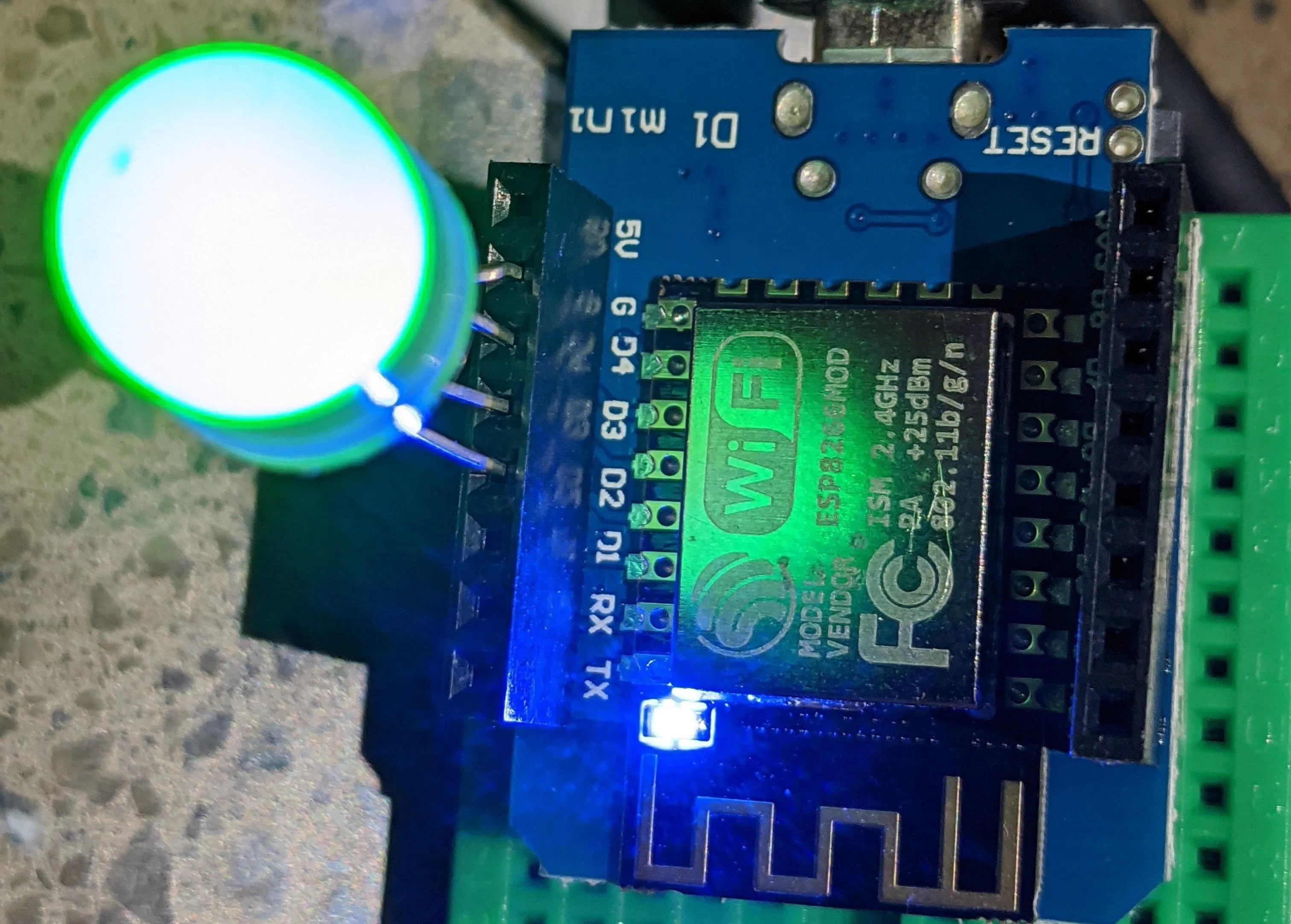
In our MicroPython REPL shell, let's run the following two lines to see if we're able to control hardware successfully. After looking up the D1 Mini's pinout diagram, we can see that the internal LED is located on pin 2, or D4 on the silkscreen.
>>> from time import sleep; from machine import Pin; led = Pin(2, Pin.OUT) # Imports modules and defines output pin 5
>>> while True: led.on(); sleep(1); led.off(); sleep(1) # Blinks LED on and off forever
...
You should see the LED on your D1 Mini start to blink off and on once per second! You can press Control-C to stop the program.
Uploading a Python Program
Now we can add an output to see if we can control external components. I'll be using an RGB LED, but you can use three regular LEDs as well. I'll be plugging the red, green, and blue wires from the LED into GPIO pins 0, 2, and 4. This works out to pins D2, D3, and D4 on the silkscreen.
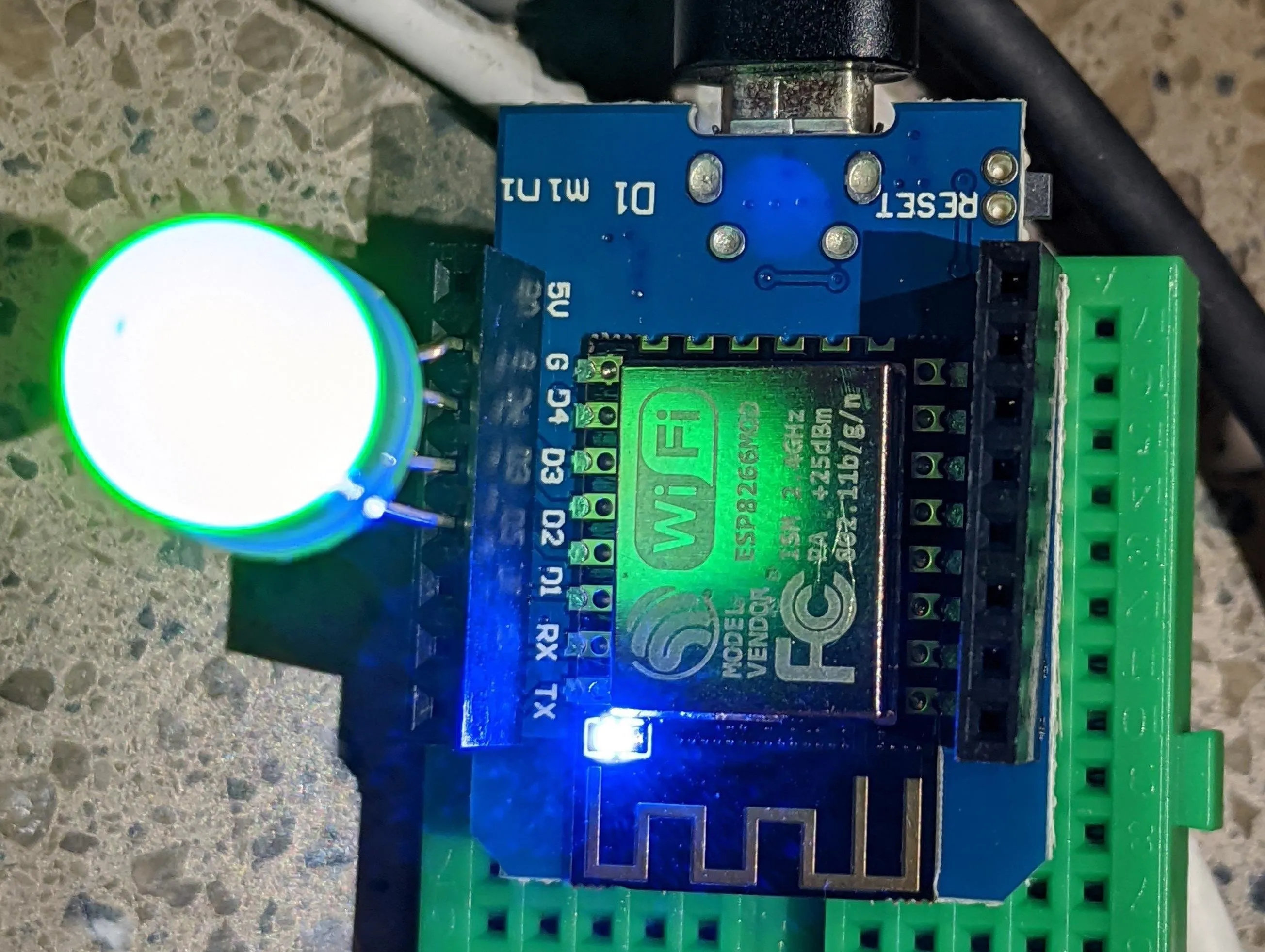
Kody/Null Byte
Now, we'll need to install Adafruit Ampy. We can do this in a fresh terminal window with the following command.
~$ pip3 install adafruit-ampy

Collecting adafruit-ampy
  Downloading https://files.pythonhosted.org/packages/59/99/f8635577c9a11962ec43714b3fc3d4583070e8f292789b4683979c4abfec/adafruit_ampy-1.0.7-py2.py3-none-any.whl
Requirement already satisfied: click in /usr/lib/python3/dist-packages (from adafruit-ampy) (7.0)
Collecting python-dotenv (from adafruit-ampy)
  Downloading https://files.pythonhosted.org/packages/57/c8/5b14d5cffe7bb06bedf9d66c4562bf90330d3d35e7f0266928c370d9dd6d/python_dotenv-0.10.3-py2.py3-none-any.whl
Requirement already satisfied: pyserial in /usr/lib/python3/dist-packages (from adafruit-ampy) (3.4)
Installing collected packages: python-dotenv, adafruit-ampy
Successfully installed adafruit-ampy-1.0.7 python-dotenv-0.10.3
Once Ampy is installed, we can use the format ampy --port /serial/port run test.py to run a Python file on our connected board. To pulse our RGB LED, type nano fades.py to create a blank Python file, then paste the following code into it.
import time; from machine import Pin, PWM; list = [0,2,4]
def PWMChange(pinNumber, intensity, delayTime): pwm2 = PWM(Pin(pinNumber), freq=20000, duty=intensity); time.sleep_ms(delayTime)
def flashing():
    for elements in list: PWMChange(elements, 0, 10)
    for elements in list:
        for i in range (0,255): PWMChange(elements, i, 10)
        if i > 253:
            for i in range(255, 0, -1): PWMChange(elements, i, 10)
while True: flashing();
Now, save the file by typing Control-X and Y to confirm. To run the file on the board, confirm you have the correct serial port and then type the following command, after swapping out /dev/cu.wchusbserial14440 for the serial port of your board.
~$ ampy --port /dev/cu.wchusbserial14440 run fades.pyYou should see the code start to run on your board! If you want your code to run at boot (but not on a loop) like an Arduino, you'll need to replace the "main.py" file on the board. You can upload our Python file and replace the main.py file on the board with the following command.
~$ ampy -p /dev/cu.wchusbserial14440 put fades.py /main.pyWith this command, our board will run the program we just uploaded, but not in a loop like an Arduino, unless you specify this with an endless loop as we did in the code above. "While true" loops run forever and don't give the board a chance to boot if they have replaced the main.py, but you can stop the program in the serial REPL by pressing Control-C and then erasing the board to fix the issue.
MicroPython Can Control Hardware in a Single Line of Code
In a few short steps, we've set up an ESP8266 microcontroller to work with MicroPython and learned the basics of working with outputs. We've also gone from running code line by line in the REPL shell to writing Python files and both running and uploading them to our board. To learn more about what you can do with MicroPython, I highly recommend checking out the official documentation on the MicroPython website.
I hope you enjoyed this guide to getting started with MicroPython on the ESP8266! If you have any questions about this tutorial on MicroPython, leave a comment below, and feel free to reach me on Twitter @KodyKinzie.
Cover photo by Kody/Null Byte


Comments
Be the first, drop a comment!