


Smartphones and other Wi-Fi enabled devices send radio signals called probe frames to locate nearby wireless networks, which makes them easy to track by listening for their unique MAC address. To show how this kind of tracking works, we can program a NodeMCU in Arduino to sniff the air for packets from any device we want to track, turning on an LED when it's detected nearby.
Tracking devices by their MAC address is done by everyone from retailers to intelligence agencies. The info is used to compile data about where people spend time and who they spend time with, which is useful for many things, such as planning traffic speeds in cities. Widespread tracking presents a serious privacy issue, though, prompting most manufacturers to implement safeguards like MAC address randomization, which protects against arbitrary monitoring of MAC addresses.
MAC Address Randomization: It Sort of Works
MAC address randomization is helpful for preventing some types of tracking, but in tests on various Android phones, it was clear the MAC address randomization is far from perfect. There are several conditions which cause a phone to revert to its real MAC address, one of which is being in proximity to a network the device has connected to before.
Upon detecting a familiar network stored in the device's preferred network list, the device will attempt to join the network and become trackable again; This can be seen in action in my post on tracking smartphones with a beacon spammer attack, in which we create many fake networks to unmask nearby devices.
In addition to seeing a Wi-Fi network in the preferred network list, being actively connected to a network will also actively reveal the permanent MAC address of the device; This means if you want to track someone coming home or walking by a coffee shop with a common network name, MAC address randomization won't get in your way.
Strangely, I observed that Samsung Android devices emit bursts of probe frames using the real MAC address any time you turn on the screen or open the Wi-Fi network selection menu. A hacker looking to grab a Samsung phone's actual MAC address only needs the person holding it to look at nearby Wi-Fi networks to send a burst of packets with the device's real MAC address.
Tracking Device MAC Addresses with Arduino
To show how easy it is to track devices, I searched for an Arduino sketch that uses the built-in Wi-Fi chip of the NodeMCU to track MAC addresses, and I found the Friend Detector; This awesome project takes any MAC address you want to monitor and sniffs the air for packets containing that address. It's really cool because the Friend Detector looks through the types of packets smartphones give off both when connected and disconnected to a Wi-Fi network, making it easier to detect a device in either condition.
Combined with the beacon swarm tactic for unmasking devices, the Friend Detector can be used to tell when a device has been successfully unmasked by the swarm of fake networks.
To make this project more visual and provide an easy way of detecting when your device is leaking its real MAC address, I decided to modify the code to include an LED and the ability to track as many MAC addresses as there are available pins to control LEDs with.
There are some issues we need to overcome when using an LED, such as the fact that using a delay to keep the LED lit for long enough to be noticeable caused the watchdog timer to kill the process and the whole thing would crash. To solve this, I added a cooldown timer that would turn on the LED when a packet with a matching MAC address is detected and keep it on until a set amount of packets were detected which did not match the MAC address we are looking for; This allows us to easily change how long the LED stays on for.
Find the Device's MAC Address
For this to work, we'll need the MAC address of the device we want to monitor. The best way to get this is to connect to a network that has the device you want to monitor and run a network scan with Fing or Nmap. Fing will not show MAC address when being run on an iPhone due to restrictions put in place by Apple, but on any other platform, this should get you the MAC address.
Get Your Materials Ready
Once you have the MAC address of the device you want to track, you'll need a NodeMCU or ESP8266-based device, a Micro-USB cable, a breadboard with either a four-pin tricolor LED or as many LEDs as devices you want to track, and computer with Arduino IDE installed to program the NodeMCU. A resistor will also be helpful, as you'll see later on.
Set Up the Arduino IDE
Before we download the Friend Detector code, we'll need to set up Arduino IDE to work with the NodeMCU. To do so, copy the following URL and paste it into the Additional Boards Manager URLs field of the "Preferences" menu. For more information on doing this, see my previous article which outlines this is more detail.
http://arduino.esp8266.com/versions/2.3.0/package_esp8266com_index.json,http://arduino.esp8266.com/stable/package_esp8266com_index.json,http://phpsecu.re/esp8266/package_deauther_index.jsonNext, you'll need to select the NodeMCU as the board you're using. To do so, install the "esp8266" board by "ESP8266 Community" in the "Boards Manager." Again, see my previous article which outlines this is more detail.
Make sure to select NodeMCU from the drop-down board list now that the board is installed. This should be everything you need to program the NodeMCU in Arduino. For more information on this whole step, see my previous article.
Add the Code & Dependencies
Next, we can download the code for the Friend Detector on GitHub, a fork of Ricardo Oliveira's original project, by simply pasting the command below into a terminal window.
git clone https://github.com/skickar/FriendDetector.gitOnce the code has downloaded, navigate to the folder the files downloaded to with:
cd FriendDetectorYou should notice that there are a few files there, and this is because the Friend Detector includes a packet sniffing library which needs to be added to our Sketch before it will work. Open the "FriendDetector" INO file in Arduino IDE, and then click on "Sketch" to show the "Add File" menu option at the end of the list. Select that, then add the "esppl_functions.h" and "esppl_struct.h" files to the Sketch. With these libraries included, we're ready to push our code to the NodeMCU.
Break Down the Code Function
To understand what this code is doing, let's take a look under the hood.
The first section of the code sets up the variables for the rest of the script. Here, we define the size of the list of MAC addresses we are tracking, the actual MAC addresses in the list, and the names of the targets associated with the MAC addresses in the list.
#include "./esppl_functions.h"

/*  Define you friend's list size here
 How many MAC addresses are you tracking?
 */
#define LIST_SIZE 2
/*
 * This is your friend's MAC address list
 Format it by taking the mac address aa:bb:cc:dd:ee:ff
 and converting it to 0xaa,0xbb,0xcc,0xdd,0xee,0xff
 */
uint8_t friendmac[LIST_SIZE][ESPPL_MAC_LEN] = {
   {0x12, 0x34, 0x56, 0x78, 0x90, 0x12}
  ,{0x34, 0x56, 0x78, 0x90, 0x12, 0x34}
  };
/*
 * This is your friend's name list
 * put them in the same order as the MAC addresses
 */
String friendname[LIST_SIZE] = {
   "Target 1"
  ,"Target 2"
  };
Next up, we have our setup section, in which we set pins D5, D6, and D7 to output so that we can use them to control an LED when we set them to "high." Next, I wrote a few functions to assign each pin to a color, so I can keep track of them later in the code. To turn on that color, we just need to use the "digitalWrite(pin, mode)" function to select the pin and whether we want to set it to high or low.
Finally, I wrote a function called "turnoff()" to turn off all the LEDs that are on if no packets are detected for long enough to run out our cooldown timer by setting all the pins to low.
void setup() {
  delay(500);
  pinMode(D5, OUTPUT); // sets the pins to output mode
  pinMode(D6, OUTPUT);
  pinMode(D7, OUTPUT);
  Serial.begin(115200);
  esppl_init(cb);
}

void red() {
digitalWrite(D5, HIGH); }  // Turn ON the red LED
void blue() {
digitalWrite(D7, HIGH); } // Turn ON the blue LED
void green() {
digitalWrite(D6, HIGH); } // Turn ON the green LED
void turnoff() {
    digitalWrite(D7, LOW), digitalWrite(D5, LOW), digitalWrite(D6, LOW);
}
Great! Now the pins are set up, and we can switch the colors on and off as needed. One small flaw here is that if we detect two devices and then one vanishes, the LED turned on by the first device will stay on even after the device is gone if the second device keeps adding to the cooldown timer. I did this so we'd only need one cooldown timer rather than one for each color, but you can modify this if you'd rather tack each device's appearance more accurately.
Now, let's jump to the part of the code that controls the logic of what happens when we detect packets. Here, we see a line that says the following.
for (int i=0; i<LIST_SIZE; i++) {
    if (maccmp(info->sourceaddr, friendmac[i]) || maccmp(info->receiveraddr, friendmac[i])) {
This means, for the same number of times as we have items in our list, attempt to match both the sending and receiving address in the packet we detected to the MAC addresses in our list. This all looks good, so let's modify what happens next when we detect a packet from or to a device we are listening for.
Here is the chunk of logic that controls what happens when we do detect a MAC address we're looking for. First, we see that we print the name of the person to serial, which you can see on your computer by clicking the "Tools" menu in Arduino IDE, then clicking on the "Serial Monitor" option. This is done using string formatting.
Now, I'll add two things: a cooldown timer and assign each MAC in the list to a color to turn on. For the cooldown timer, I set the value to 1000, but you can adjust this depending on your needs. What this means is that each time we detect a packet from a MAC we know, the light will stay on until 1000 packets have been detected that do not match any of the devices on our list. I did this to get around the problem with not being able to create a delay to keep the LED on.
void cb(esppl_frame_info *info) {
  for (int i=0; i<LIST_SIZE; i++) {
    if (maccmp(info->sourceaddr, friendmac[i]) || maccmp(info->receiveraddr, friendmac[i])) {
      Serial.printf("\n%s is here! :)", friendname[i].c_str());
      cooldown = 1000; // here we set it to 1000 if we detect a packet that matches our list
To control the LED color, I used an "if" statement that says if we have detected a packet with a MAC matching one in our list, light up a color according to the position of the matching MAC address in that list. Because most lists start at 0 in programming, an example would be that the first MAC address on the list would be index 0 and set to red. The second MAC address would be index 1 and set to blue. And the third would be index 2 and be set to green.
Because I'm only using two MAC addresses for this example, I can just pick one of the elements and then use the "else" clause to specify the other color. The reason this works for two MAC targets is because, to get this far in the code, we must have detected a packet that matches one of the two items in the list, and if it doesn't match the first index we specified, it must be the remaining one.
if (i == 1){
        blue();} // Here we turn on the blue LED until turnoff() is called
        else {
          red();} // Here we turn on the RED LED until turnoff is called. We can also use if i == 0, or another index
    }
Now, let's define what happens when the packet does not match any of the MAC addresses in our list.
else { // this is for if the packet does not match any we are tracking
        if (cooldown > 0) {
          cooldown--; } //subtract one from the cooldown timer if the value of "cooldown" is more than one
          else { // If the timer is at zero, then run the turnoff function to turn off any LED's that are on.

        turnoff(); } } } }
Here, we say that if the cooldown timer is greater than zero, subtract one from the cooldown timer. If the cooldown timer is at zero, run the "turnoff()" function to turn off any LEDs that are on.
The last part of the code manages the channel hopping, and we won't be touching it for this demonstration.
The final completed code should look like this:
/*
Friend Detector by Ricardo Oliveira, forked by Skickar 9/30/2018

A Node MCU microcontroller + mini bread board + 4 pin RGB LED to detect when devices belonging to a target are nearby.

The function of this code is to read nearby Wi-Fi traffic in the form of packets. These packets are compared
to a list of MAC addresses we wish to track, and if the MAC address of a packet matches one on the list, we turn
on a colored LED that is linked to the user owning the device. For example, when my roommate comes home, the
transmissions from his phone will be detected and cause the blue LED to turn on until his phone is no longer detected.
It can detect more than one phone at a time, meaning if my phone (red) and my roommate's phone (blue) are both home,
the LED will show purple. */

#include "./esppl_functions.h"

/*  Define you friend's list size here
 How many MAC addresses are you tracking?
 */
#define LIST_SIZE 2
/*
 * This is your friend's MAC address list
 Format it by taking the mac address aa:bb:cc:dd:ee:ff
 and converting it to 0xaa,0xbb,0xcc,0xdd,0xee,0xff
 */
uint8_t friendmac[LIST_SIZE][ESPPL_MAC_LEN] = {
   {0x12, 0x34, 0x56, 0x78, 0x90, 0x12}
  ,{0x34, 0x56, 0x78, 0x90, 0x12, 0x34}
  };
/*
 * This is your friend's name list
 * put them in the same order as the MAC addresses
 */
String friendname[LIST_SIZE] = {
   "Target 1"
  ,"Target 2"
  };

// start variables package - Skickar 2018 hardware LED for NodeMCU on mini breadboard //
void setup() {
  delay(500);
  pinMode(D5, OUTPUT); // sets the pins to output mode
  pinMode(D6, OUTPUT);
  pinMode(D7, OUTPUT);
  Serial.begin(115200);
  esppl_init(cb);
}

/* You cannot use a time delay here to keep the LED on, so will need to use ratio of
detected packets to overall packets to keep LED on for longer. If you try to use a
delay to keep the light on for long enough to be useful, the watchdog timer kills the
process and it dies */
int cooldown = 0; /* This variable will be a cooldown timer to keep the LED on for longer, we'll set it to 1000 if we
detect a packet from a device with a MAC address on the list, and then keep the LED on till we get 1000 packets that
are NOT from any device on the list. */
void red() {
digitalWrite(D5, HIGH); }  // Turn ON the red LED
void blue() {
digitalWrite(D7, HIGH); } // Turn ON the blue LED
void green() {
digitalWrite(D6, HIGH); } // Turn ON the green LED
void turnoff() {
    digitalWrite(D7, LOW), digitalWrite(D5, LOW), digitalWrite(D6, LOW);
}

/* end exparimental variable package */

bool maccmp(uint8_t *mac1, uint8_t *mac2) {
  for (int i=0; i < ESPPL_MAC_LEN; i++) {
    if (mac1[i] != mac2[i]) {
      return false;
    }
  }
  return true;
}

void cb(esppl_frame_info *info) {
  for (int i=0; i<LIST_SIZE; i++) {
    if (maccmp(info->sourceaddr, friendmac[i]) || maccmp(info->receiveraddr, friendmac[i])) {
      Serial.printf("\n%s is here! :)", friendname[i].c_str());
      cooldown = 1000; // here we set it to 1000 if we detect a packet that matches our list
      if (i == 1){
        blue();} // Here we turn on the blue LED until turnoff() is called
        else {
          red();} // Here we turn on the RED LED until turnoff is called. We can also use if i == 0, or another index
    }

      else { // this is for if the packet does not match any we are tracking
        if (cooldown > 0) {
          cooldown--; } //subtract one from the cooldown timer if the value of "cooldown" is more than one
          else { // If the timer is at zero, then run the turnoff function to turn off any LED's that are on.

        turnoff(); } } } }

void loop() { // I didn't write this part but it sure looks fancy.
  esppl_sniffing_start();
  while (true) {
    for (int i = ESPPL_CHANNEL_MIN; i <= ESPPL_CHANNEL_MAX; i++ ) {
      esppl_set_channel(i);
      while (esppl_process_frames()) {
        //
      }
    }
  }
}
When we're satisfied with our changes, we can click the check mark to compile and check our code for errors, and then the arrow button to send the Sketch to our NodeMCU, which should be connected via a Micro-USB cable. After the Sketch finishes sending, we can start to wire our breadboard and test the program.
Wire the Breadboard
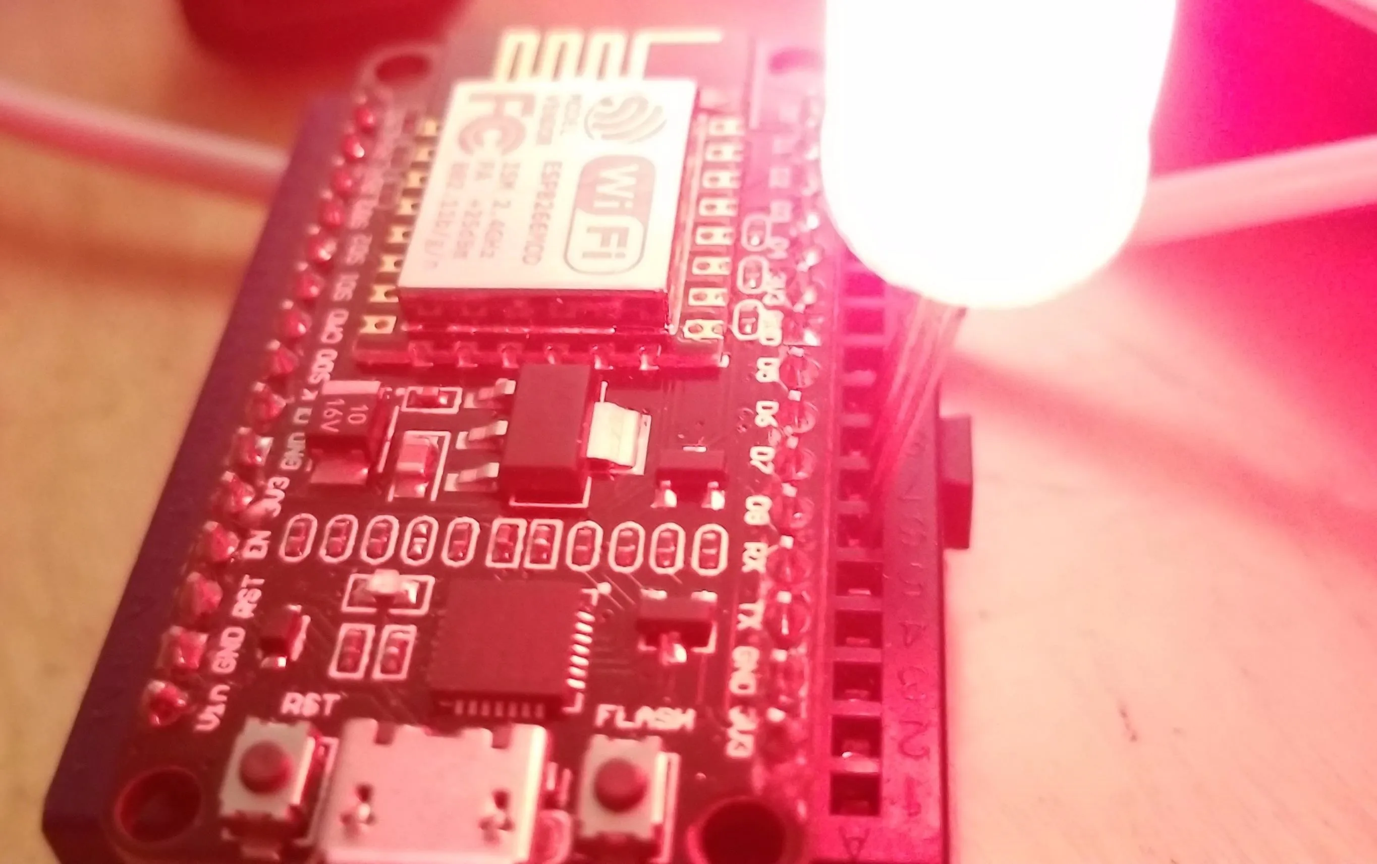
I've kept the layout extremely simple in this code, using the D5, D6, and D7 pins to control a different colored LED. I picked those pins because D5 is right next to a ground pin on the NodeMCU, allowing me to just stick a four-pin RGB LED into the ground, D5, D6, and D8 row of a breadboard directly next to the pins.
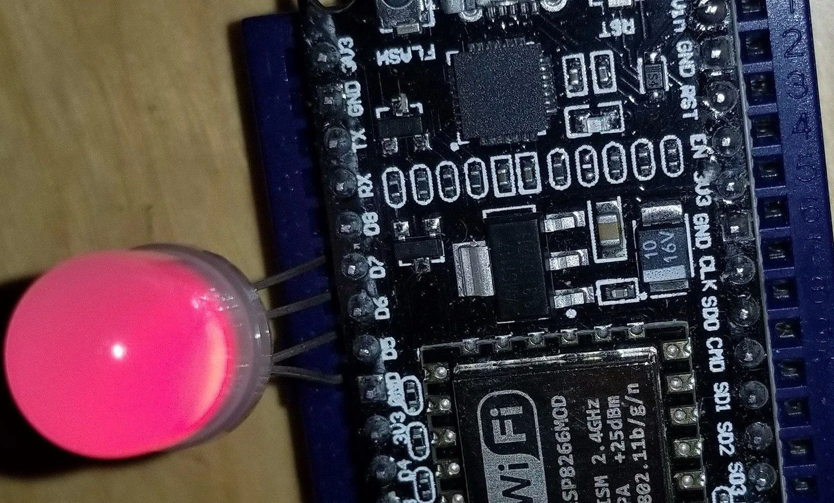
Kody/Null Byte
If you want to save your LEDs, I recommend instead wiring the D5, D6, and D7 pins to the LED in a different spot on the board, and then adding a resistor (or a potentiometer) between the ground pin and the row of the breadboard you're using to ground the LEDs to reduce the voltage and prolong the life of the LEDs.
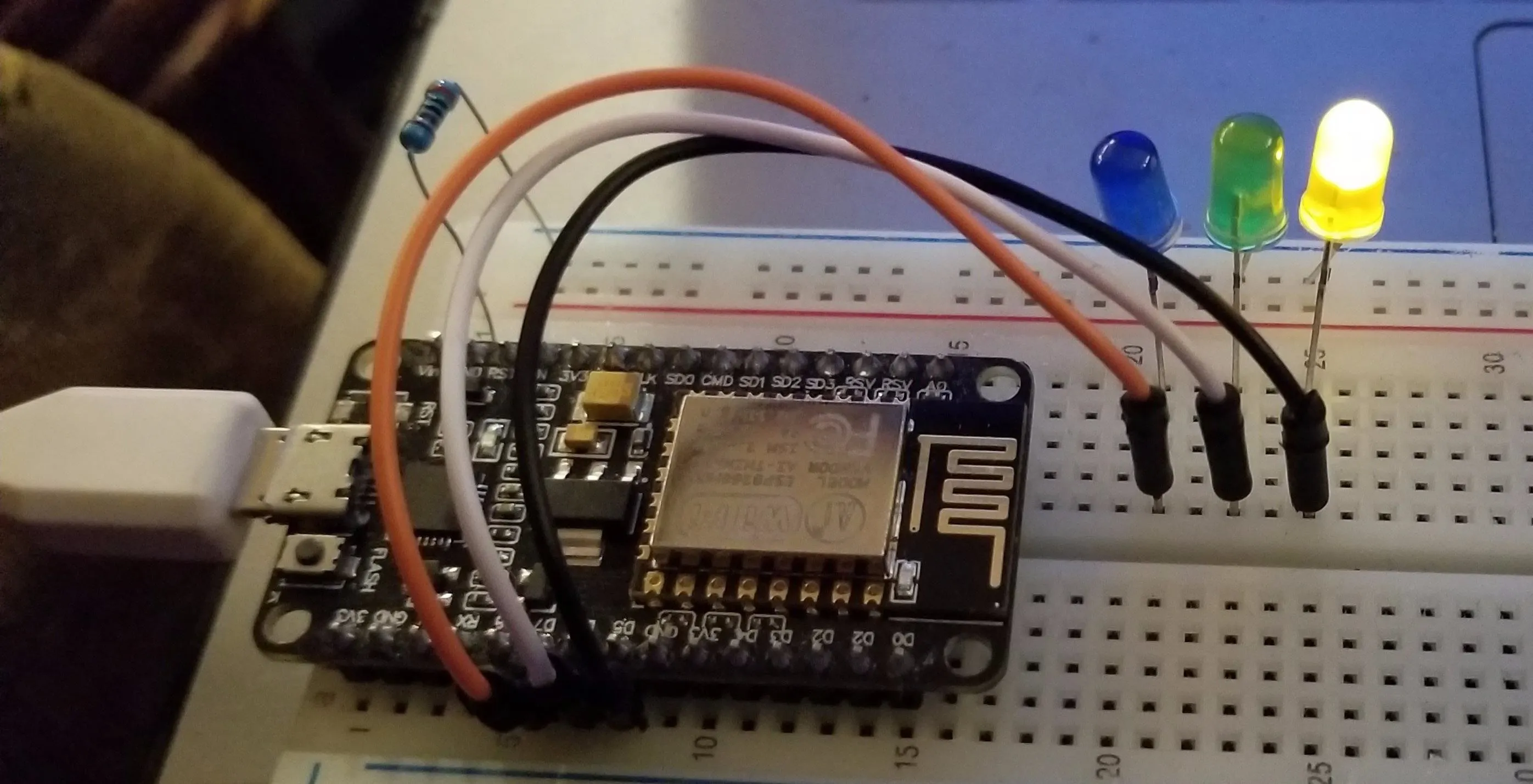
Kody/Null Byte
As you can see in these pictures, there are a few possible layouts, but all have a few things in common.
If you are attaching an LED to any of the pins (the longer of the two LED legs is the one that connects to the pin), the other side must connect to ground in order to function. You can place a resister either between the pin of the NodeMCU and the LED or between the ground pin and the LED; Both will have the same effect of reducing the electrical flow to prolong the life of the LED, as too much voltage can burn it out.
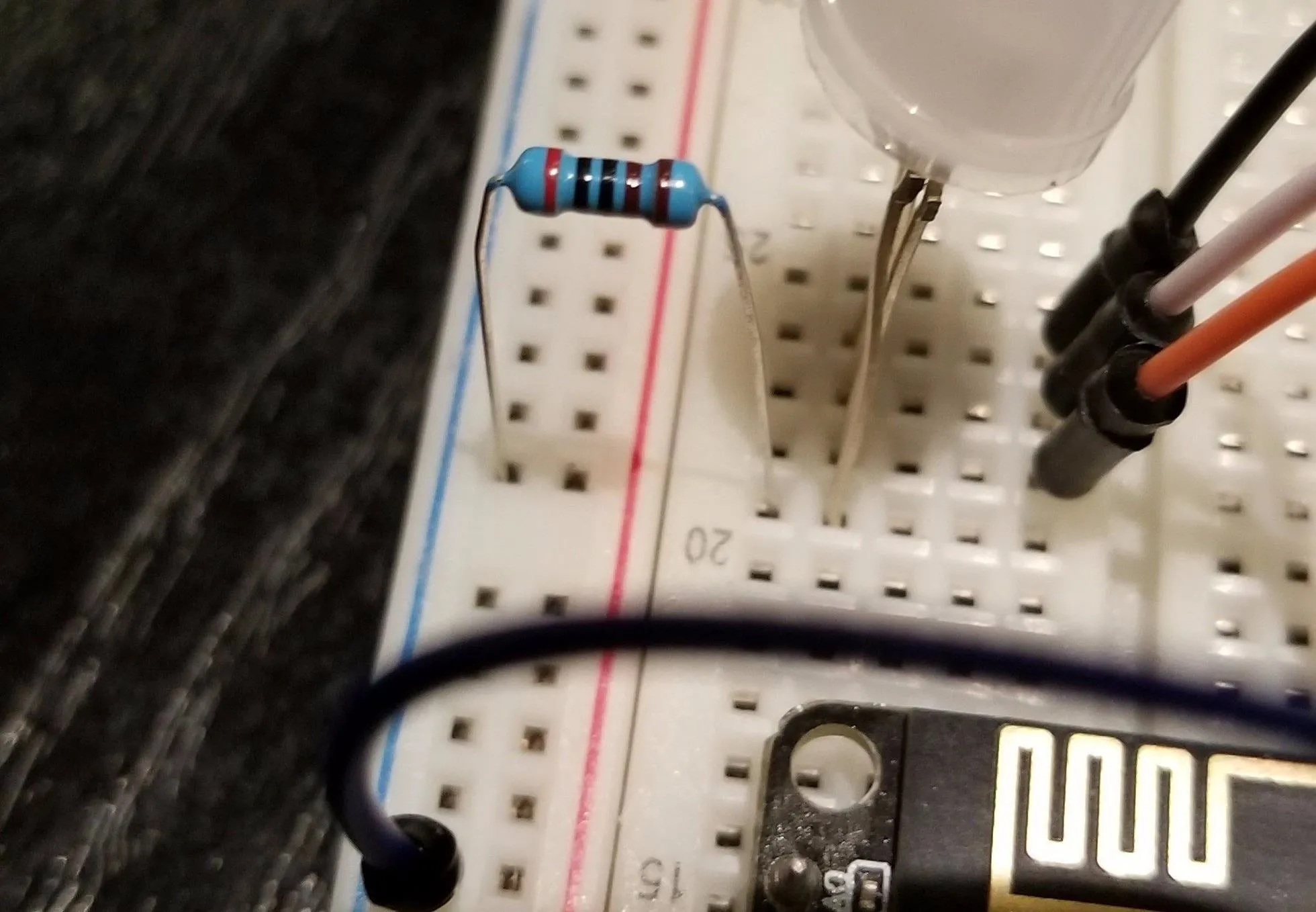
Kody/Null Byte
If at any time you look at your LED lit up and immediately think, "Wow, that's really bright," you should probably add a resistor.
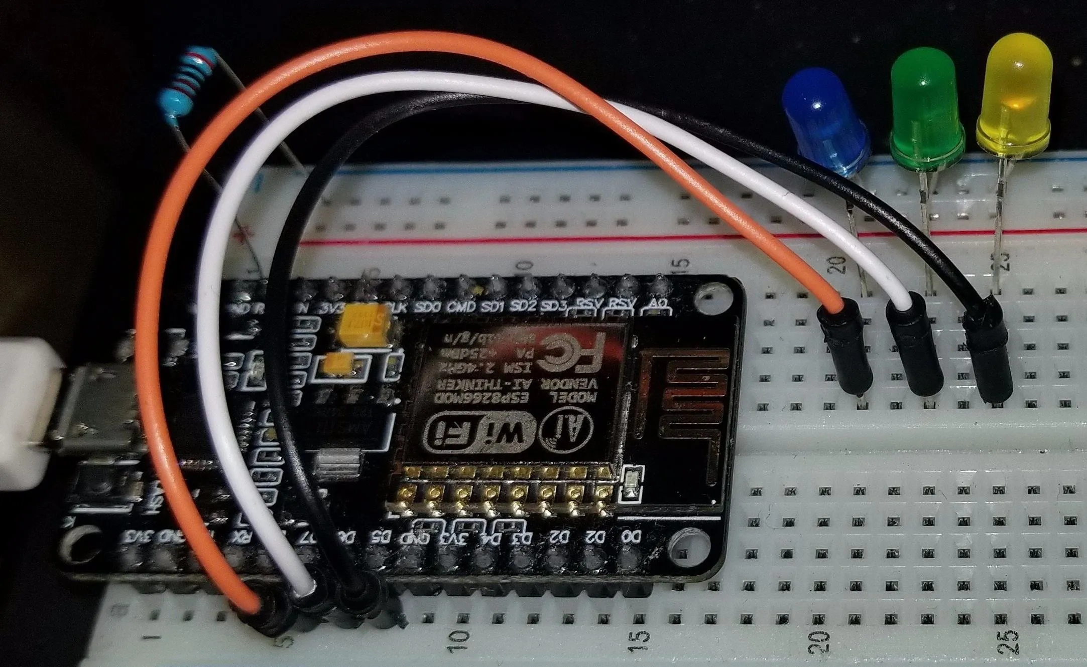
Kody/Null Byte
Once you have the LED wired, you can test the connections by adding a wire to the pin marked "3.5v" and then, very, very briefly, tapping it against the positive leg of the LED. If it lights up, everything is connected and you're ready to begin your test.
Test the MAC Address Detector
To test our ability to detect a device with a MAC address added to our tracking list, we can do a few things to stimulate a burst of packets.
On an Android phone, this is often as simple as activating the screen of the phone while the Wi-Fi is turned on. On an iPhone, it might take a little more interaction. An iPhone automatically connecting to a network that it has connected to before, or being presented with a swarm of fake networks like in our beacon swarming attack, will also reveal its real MAC address. Both of these will cause the kind of signals our Friend Detector will react to.
Kody/Null Byte
In practice, a way you can take advantage of this is to set up a network you know the target's phone will react to in proximity to the Friend Detector and simply wait for the device to decloak itself on the same channel. The addition of an "active" decloaking element greatly increases the effectiveness of the detector, but that is a more advanced design than we will cover today.
After turning on your Wi-Fi and connecting to a nearby Wi-Fi network if necessary, you should see the LED light up when one of the devices on the list is detected. When this happens, you've successfully created a MAC address sniffer! You can make this project even more useful by adding a directional antenna, allowing you to start hunting for the direction of the device as soon as it is detected.
Countermeasures Against MAC Address Tracking
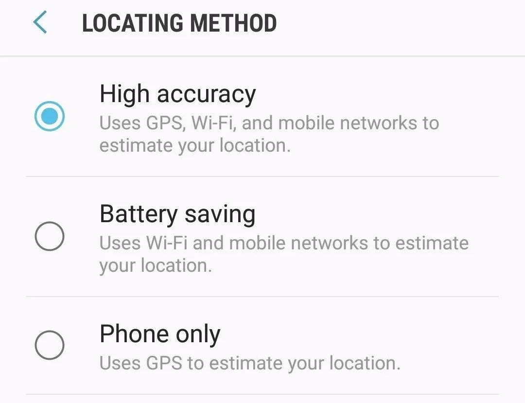
While the most obvious countermeasure is to turn your Wi-Fi card off when you don't need it, this may not actually work for all devices. Some devices will continue to emit probe requests to identify the device's location as part of assisted-GPS, or aGPS. You can disable this by going into the GPS and disabling a setting that's called "High accuracy" GPS or similar.
While airplane mode may be an acceptable option for some users, the majority would find cutting off all communications to their device too inconvenient for the added benefit of privacy.
For added safety and privacy, you should also go through your device and delete any networks you no longer connect to, especially any networks that don't require a password. These networks being stored in your phone allow anyone to create a network with the same name and either decloak or take over your device's data connection.
I hope you enjoyed this guide to detecting when devices are nearby by tracking their MAC address! If you have any questions about this tutorial on Wi-Fi tracking or you have a comment, feel free to reach me on Twitter @KodyKinzie.
- Follow Null Byte on Twitter, Flipboard, and YouTube
- Sign up for Null Byte's weekly newsletter
- Follow WonderHowTo on Facebook, Twitter, Pinterest, and Flipboard
Cover photo and screenshots by Kody/Null Byte


Comments
Be the first, drop a comment!