
Wireless devices are everywhere, sometimes the protocol is not well documented because the manufacturer is relying upon security by obscurity. This guide is designed to give you the essential tools to start evaluating radio signals. Many common devices might include wireless alarm systems, keyboards, building access controls (garage door openers), and even smart electric meters. There can be dire consequences if the rush to implement this technology was not met with an equal desire to make it secure.
Understanding the protocol can help you evaluate the security, or lack thereof, in a given device. Problems cannot be fixed if they are not first identified. This guide will focus on digital signals. Digital signals are often more interesting and analog signals are generally limited to a few modulation methods that are well documented and can easily be demodulated with existing tools.
Radio Reverse Engineering Environment
For this guide I will use a RTLSDR dongle in Kali Linux. These devices are very inexpensive and provide adequate results. I will use an old, now unused, garage door opener as my mystery radio transmitter. You can use anything, however some devices can be more complicated than others to decode, especially newer ones with more security built in. For software I will use Universal Radio Hacker (URH).
Step 1: Install URH
Open a terminal in Kali linux and type the following. If you are not using Kali linux with an RTLSDR you may want to check the authors website for detailed instructions on your particular operating system and radio device.
apt update
apt upgrade -yapt install -y librtlsdr-dev python3-numpy python3-psutil python3-zmq python3-pyqt5 g++ libpython3-dev python3-pip cython3
pip3 install urh
Step 2: Locate the Frequency of the Device
The first thing to know about a device is the frequency it operates on. If you have a device sold in the US (even if you got it in a different country) you can look for the FCC ID number. Mine is HBW0709 If your device no longer has a label you can try googling for the exact model number and adding "fccid" and you might get lucky. Often devices will be in a similar frequency range when made for global audiences even if it is not exact.
Once you have located the FCC ID you can perform a search on the FCC database. fccid.io is a good resource for this type of searching and presents the data in an easy to read format. My garage door opener is 390MHz.
Step 3: Configure URH
Connect your RTLSDR to an available USB port on your computer. Then launch URH.
urh
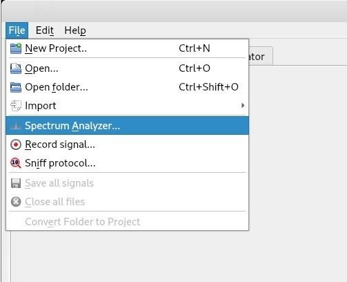
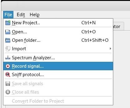
The next step is to verify that we have the correct frequency. Do this by running the spectrum analyzer built into URH.
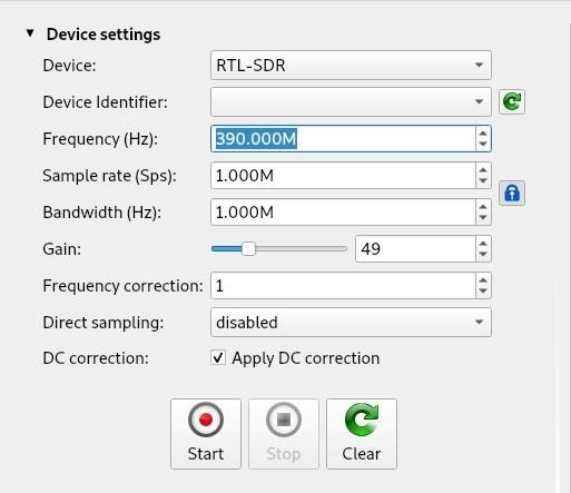
Ensure that the device is set to RTL-SDR and set the frequency to the frequency the device you are reversing is using.
Step 4: Verify the Frequency
Click "Start" and a line plot along with a waterfall plot will be displayed. Activate the device, in the case of a garage door opener this is as simple as pressing one of the buttons. Then release the button. You should see activity that coincides with your button presses.
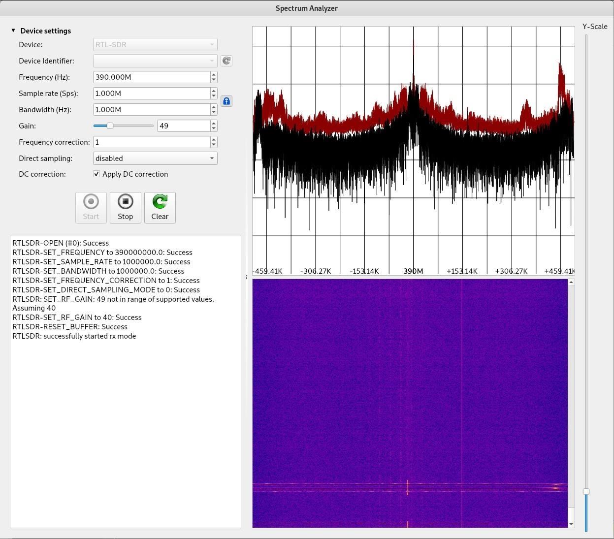
In the waterfall (the largely blue-purple portion) you can see a vertical line where I pressed the button. This confirms the correct frequency (or a harmonic but more likely the correct frequency).
Step 5: Record a Signal for Analysis
Next you will want to record the signal so you can play it back as many times as is needed. This can make it much easier to analyze, especially if you cannot always control when the device transmits such as with an embedded system.
The interface is almost identical to the spectrum analyzer interface. Enter the correct frequency and click start.
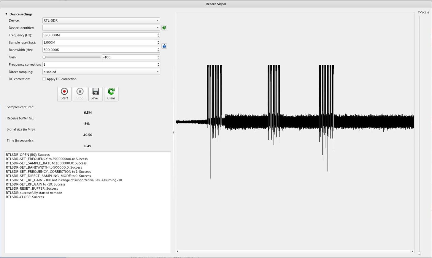
Because I am close to the transmitting device I turned the gain all the way down to reduce noise. Then activate the radio device. My device has 3 buttons, I pressed them one at a time until all 3 had been pressed. Finally click stop to end recording.
Click save and select a file name and path to store the data.
Step 6: Prepare to Analyze the Data
The first step in analyzing unknown protocols should be an attempt to locate as much information as possible. Unfortunately with this particular device it is too old (circa 1994) that there are no archived documents at the FCC to inspect.
I do know that this device has 3 buttons, each of which can control a separate function. I was able to locate a user manual which stated that the device has a fixed code and the receiver must be programmed to remember that device is authorized, down to which button specifically is pressed.
This is not much information. Multiple devices would help me differentiate what is the opener code and what is regular data but alas I do not have any additional openers from 1994 (although there do appear to be some on ebay so it could be done).
Multiple devices are almost always required to fully reverse a protocol, however that is often just repeating the steps here and looking for differences in the data and attempting to understand them.
Step 7: Lets Analyze
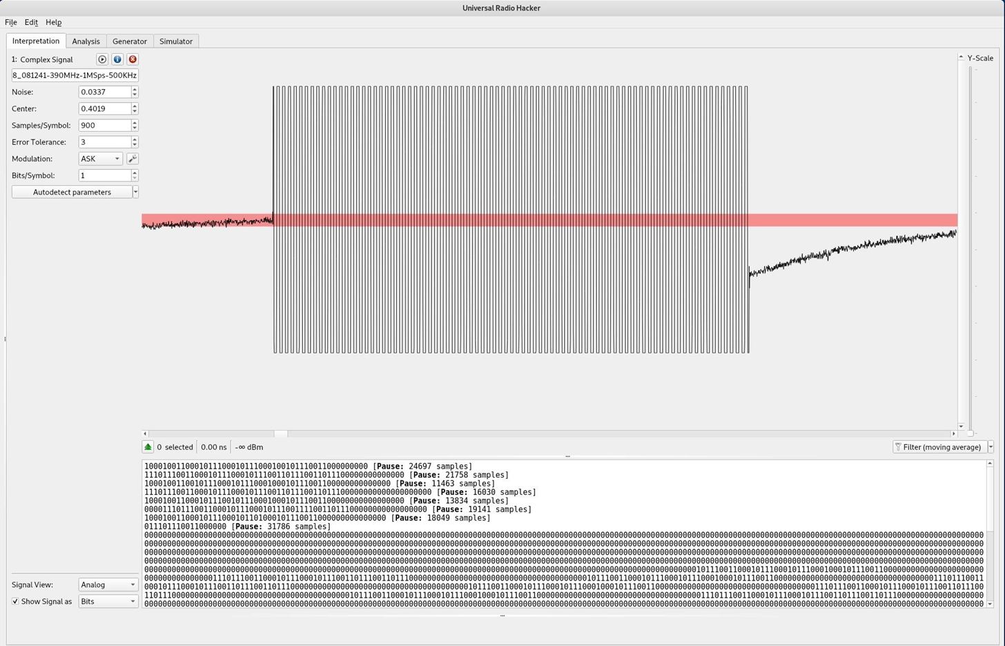
Going back to the main window of URH we can open the file we just saved. Using the mouse wheel we can zoom in and look at the signal itself. Data is transmitted in a few different ways. In this particular example we can see that the modulation has a uniform frequency. This means it cannot be FSK (Frequency Shift Keying). It also does not have the phase shifts, which often manifest as a double bump on a sine wave, so it cannot be PSK (Phase Shift Keying). It appears to use ASK (Amplitude Shift Keying) with 2 states, "on" and "off" which makes it fairly straight forward to translate into binary.
Next I want to isolate each of the 3 button presses for easier analysis. I highlight the first section, right click and then choose "create signal from selection."
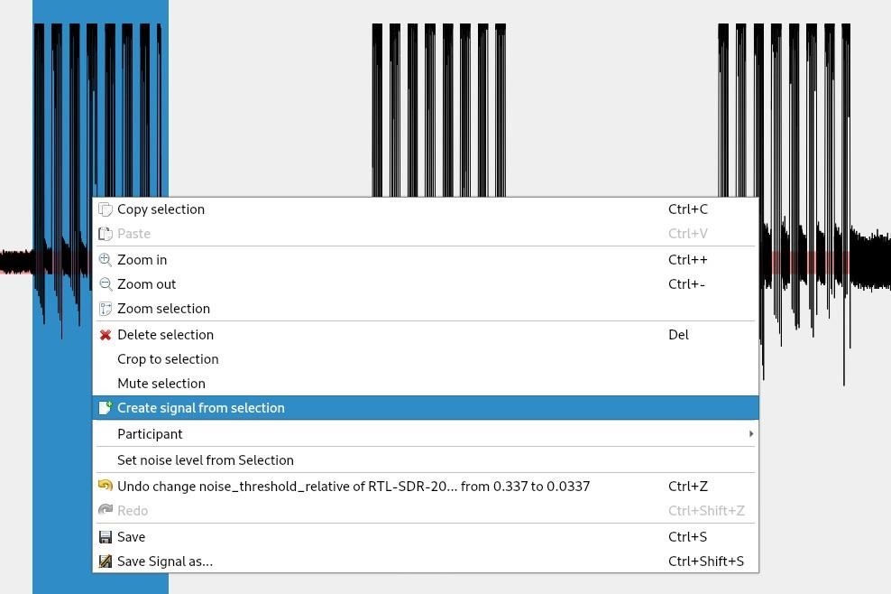
I repeat this for each of the 3 button press events.
Due to the fact that my RTLSDR is of particularly low build quality there is a lot of noise present. This noise is especially problematic in decoding the first and last bits of data as they often become corrupted. If your radio is similarly cheaply made then I suggest you take multiple samples to ensure at least one good quality read.
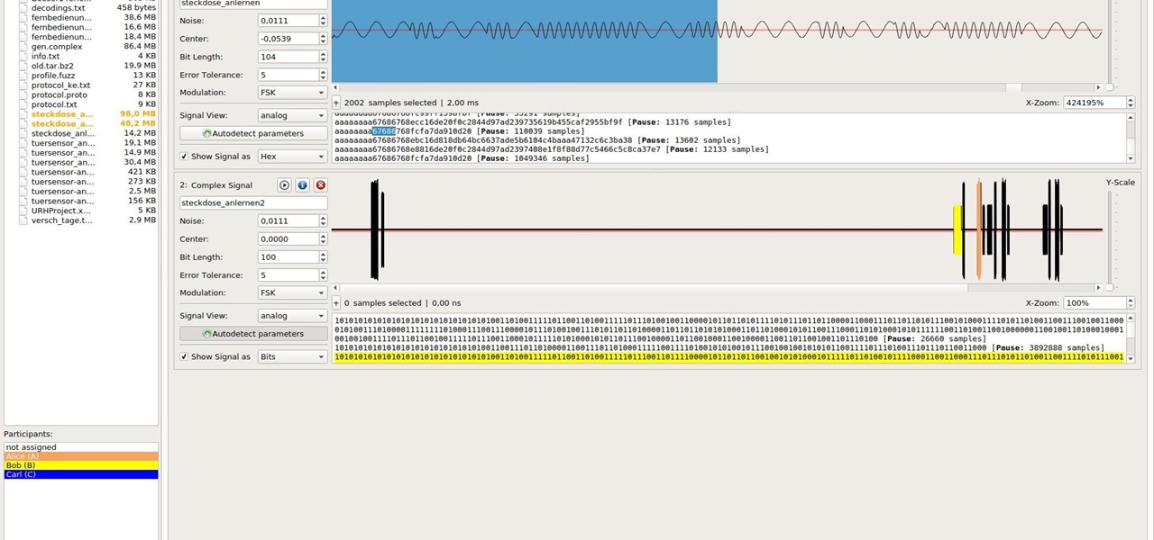
In order to get a clean signal I increase the noise value, in this case by a factor of 10. Instantly a pattern emerges. There are two sets of data transmitted in each of the 3 button presses which repeat. The first one is slightly different for each button, the second one is the same.
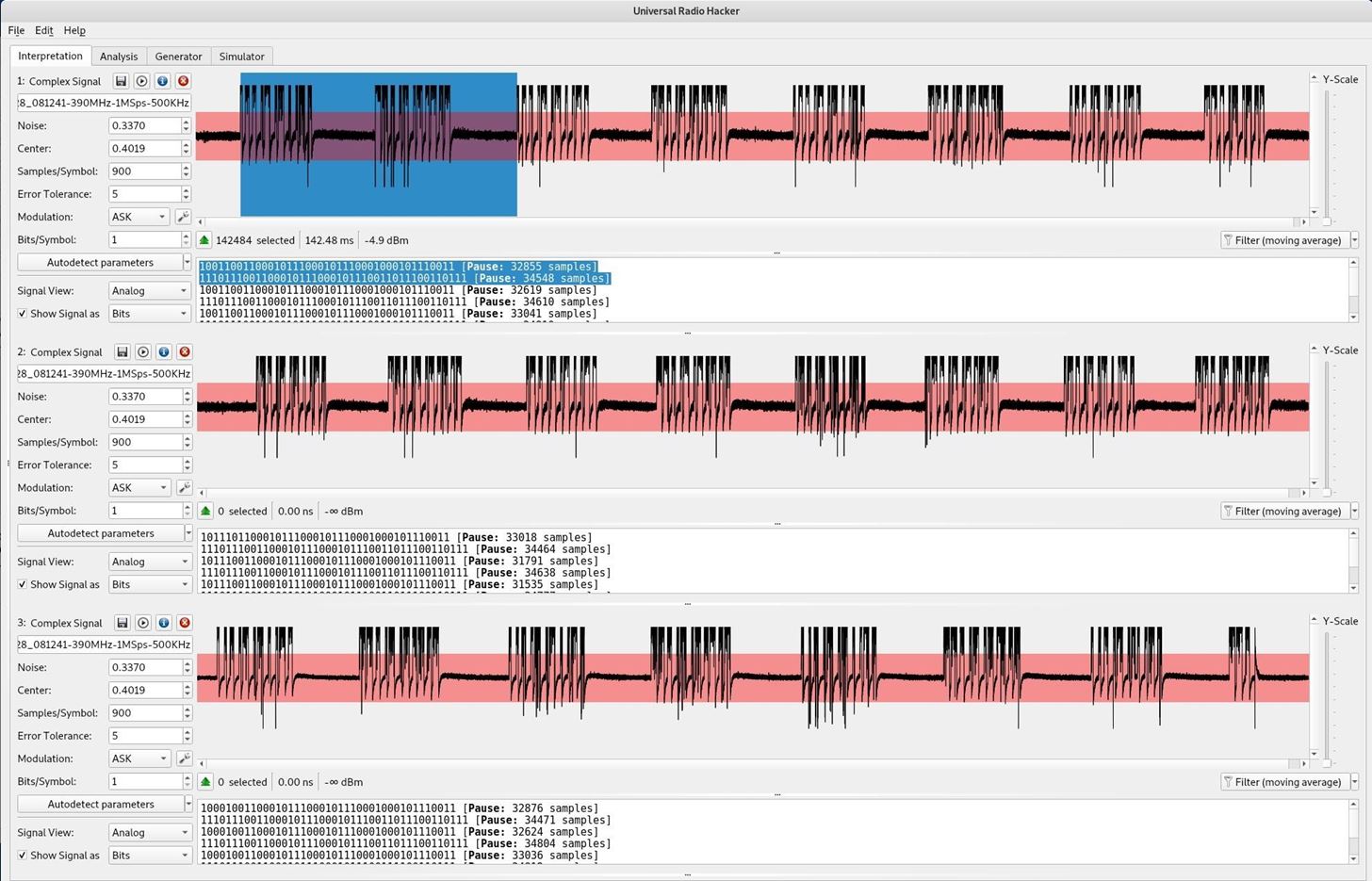
By clicking on the Analysis tab you can view the data in a variety of formats and for complex data patterns you can differentiate between different packets to see what changed.
Here we can see one button (lines 1 & 2) transmitted
89 8b 85 c4 5c c
ee 62 e1 73 73 7
A different button (lines 11 & 12) transmitted
b9 8b 85 c4 5c c
ee 62 e1 73 73 7
The final button (lines 17 & 18) transmitted
99 8b 85 c4 5c c
ee 62 e1 73 73 7
Only the first nybble of the first byte changed. We have the values in binary 1000, 1011, 1001. From this limited data set the first nybble or perhaps only the last 2 bits represent the button code. If another similar device was analyzed the same way differences could be located which might identify if the ee62... portion is part of the device code or if it is part of the framing.
If I were to guess at this point I would guess at least some, if not all of it is framing. The final characters are 73737 where repeating patterns are often used to frame data or synchronize both parties. hex A and 5 are also commonly used for this purpose. Because they are 25 year old garage door openers and not very practical outside of an academic project I am not sure this would be beneficial.
Conclusion
While the subject matter is a silly garage door opener from a quarter century ago the techniques utilized can be applied to any radio signal. Not every tool will work as well. URH does not appear to do QAM or some of the other digital modes that exist. You may have to find a suitable tool once you have identified the modulation type to help you analyze the signal.
The basic steps for an unknown signal would be:
- OSINT (Open Source Intelligence) - vendor webpage, FCC, and other public resources;
- Identify the frequencies and bandwidth it transmits on;
- Discern the modulation being used. Google can be of help as there are many images of graphs to compare against;
- Figure out how fast it is transmitting data - here URH told us, but you may need to measure how often a symbol is transmitted;
- Identify if there is a preamble (possibly 10 in the above example) or any sequence of bits to wake the device up and frame a packet. This can be aided by multiple similar devices; and,
- Extract the data - once you have the data you may need to do further analysis to understand what it means.


Be the First to Respond
Share Your Thoughts